Welcome to Roger Russell's
McIntosh Driver and Crossover History plus Service Information
including crossover networks,
parts and hardware.
These pages are copyrighted
No portion of this site may be reproduced in whole or in part
without written permission of the author.
Component speakers should really be referred to as drivers to avoid confusion with speaker systems that are also referred to as speakers. All Mcintosh part numbers are divided into different families. The first three numbers 036 designate the family of drivers and the last 3 numbers identify the specific driver. A number 036-035, for example, will be found on a label on the back of a mid-range driver made by McIntosh. Some early drivers were made by United Speaker Systems and may not have a label. Some of the missing numbers in my list are for drivers that were not used.
![]() What's On These Pages?
What's On These Pages?
|
Important Changes Made in Speaker Sensitivity, Impedance, Response Tolerance and Power Rating |
![]()
Detailed information on many drivers including pictures
System Service information
|
W = Woofer |
T = tweeter |
|
CS350 DDS-01 HT1 HT2 HT3 HT3F & HT3W HT4 HT4 THX HT5 LS310 LS320 LS330 LS340 LS350 LS360 ML1C ML2C |
ML2M ML4C ML4M ML10C PS112 SL1 SL4 SL6 ST1 ST2 ST3 ST4 WS200 WS210 WS220 XD715 |
XD717 XE10 XL1 XL10 XR3 XR5 XR7 XR14 XR16 XR17 XR19 |
XR230 XR240 XR250 XR290 XR1051 XR1052 XRT18 XRT20 XRT22 XRT24 XRT25 XRT26 XRT26J |
![]()
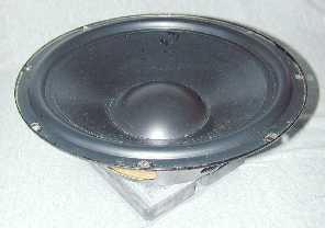 Here's a 12" woofer 036-001 used in the ML
systems that was supposedly repaired because the foam surround had
deteriorated. Instead of replacing the foam surround, which was all that was
needed, the repair service installed an entire new and different cone, voice
coil, spider and surround assembly. The cone is heavier than the original one
with the addition of a wet look laminate. The surround is made of rubber that is
also heavier. The 4-1/4" Diameter dust cover is made of rigid plastic that
is heavier than the original felt cover. This new cone assembly was used only
in McIntosh systems made after 1992. It was used in conjunction with a new cast
basket and new magnet assembly.
Here's a 12" woofer 036-001 used in the ML
systems that was supposedly repaired because the foam surround had
deteriorated. Instead of replacing the foam surround, which was all that was
needed, the repair service installed an entire new and different cone, voice
coil, spider and surround assembly. The cone is heavier than the original one
with the addition of a wet look laminate. The surround is made of rubber that is
also heavier. The 4-1/4" Diameter dust cover is made of rigid plastic that
is heavier than the original felt cover. This new cone assembly was used only
in McIntosh systems made after 1992. It was used in conjunction with a new cast
basket and new magnet assembly.
The result of the added weight is to reduce the sensitivity by 3-1/2 dB and the response no longer has the correct shape to complement the required MQ equalizer. This woofer output is now too low to properly match the original mid-range driver and now the system appears to be bass deficient. The rigid dust cap causes a 5 dB peak in the woofer response at 1.6kHz which does not entirely disappear even when used with the crossover network. The "repaired" driver will no longer work properly with the ML or XR systems where it was originally used.
![]()
 Decorative rings were added to the XL1W, XR17, XRT18,
XRT22, XR250, XR1051 and XR1052 speaker systems. The cast rings were made to
fit the McIntosh 12" and 10" woofers plus the 8," 6" and
5" mid-range drivers. Although a few systems and literature pictures show
a silver circle on the ring, management decided the ring should be all black
and most of production was made that way.
Decorative rings were added to the XL1W, XR17, XRT18,
XRT22, XR250, XR1051 and XR1052 speaker systems. The cast rings were made to
fit the McIntosh 12" and 10" woofers plus the 8," 6" and
5" mid-range drivers. Although a few systems and literature pictures show
a silver circle on the ring, management decided the ring should be all black
and most of production was made that way.
 The decorative ring really served a more important
purpose, but only for the woofers. It allows a woofer to be held in place with
foam tape on either side of the basket. This mechanically isolates the woofer
from the cabinet and eliminates all secondary cabinet vibration that was
impossible to eliminate with other kinds of bracing and/or thicker cabinet
walls.
The decorative ring really served a more important
purpose, but only for the woofers. It allows a woofer to be held in place with
foam tape on either side of the basket. This mechanically isolates the woofer
from the cabinet and eliminates all secondary cabinet vibration that was
impossible to eliminate with other kinds of bracing and/or thicker cabinet
walls.
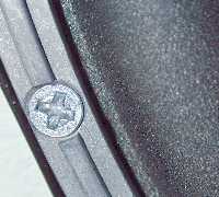
Foam tape is attached to the underside of the driver basket and the driver is placed in the cabinet. Then, two pieces of foam tape are placed at eight points around the perimeter of woofer basket. The top piece in the picture shows the impression where the mounting ring had been. The half roll of the woofer surround is at the upper left in the picture. A smaller piece of tape is under the large piece. The ring is then placed on the tape pieces and fastened to the cabinet with 4 mounting screws. The speaker is then held in place by the foam ring and foam pieces. Narrow strips of foam are also placed under the ring to prevent vibration between the ring and the cabinet.
![]()
 The XR290
woofer and mid-range drivers are mounted differently from the other systems. An
intermediate cast metal mounting ring is used. The woofer is placed in the
cabinet with foam tape between the back of the basket and the cabinet. The ring
is then placed at the perimeter of the basket. Eight flat head screws are then
used to hold the woofer assembly in place. Four screws are used for the
mid-range.
The XR290
woofer and mid-range drivers are mounted differently from the other systems. An
intermediate cast metal mounting ring is used. The woofer is placed in the
cabinet with foam tape between the back of the basket and the cabinet. The ring
is then placed at the perimeter of the basket. Eight flat head screws are then
used to hold the woofer assembly in place. Four screws are used for the
mid-range.
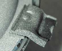
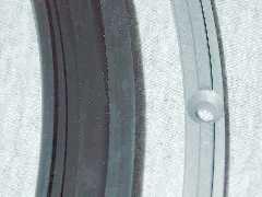
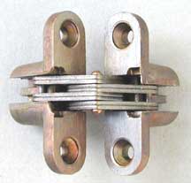
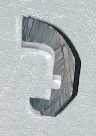 A molded decorative rubber ring is then fitted over
the cast ring. As a result, there are no visible screws. The picture at the
left shows the underside of the rubber ring where the casting fits. A cross section
of the rubber ring is shown in the picture at the right. The outside surface of
the ring is a satin texture. The rubber is sulfur free to prevent staining of
nearby surfaces over time.
A molded decorative rubber ring is then fitted over
the cast ring. As a result, there are no visible screws. The picture at the
left shows the underside of the rubber ring where the casting fits. A cross section
of the rubber ring is shown in the picture at the right. The outside surface of
the ring is a satin texture. The rubber is sulfur free to prevent staining of
nearby surfaces over time.
![]()
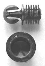
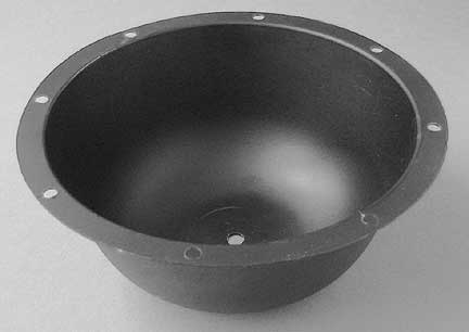 I needed some kind of containment to isolate the 8”
mid-range driver from the rest of the enclosure. Only a small volume was
needed. In my first ML-1C prototype, I used a thick plastic salad bowl called a
“Bongo Bowl” that I found at Sears. I glued it in place on the inside of the
enclosure with silicone RTV adhesive. When we went into production, a vacuum
formed plastic was used instead. The bowl was roughly shaped like a hemisphere.
A hole in the bottom was provided for the wires along with a Heyco strain
relief and caulking compound. Eight holes in the rim were provided for
mounting.
I needed some kind of containment to isolate the 8”
mid-range driver from the rest of the enclosure. Only a small volume was
needed. In my first ML-1C prototype, I used a thick plastic salad bowl called a
“Bongo Bowl” that I found at Sears. I glued it in place on the inside of the
enclosure with silicone RTV adhesive. When we went into production, a vacuum
formed plastic was used instead. The bowl was roughly shaped like a hemisphere.
A hole in the bottom was provided for the wires along with a Heyco strain
relief and caulking compound. Eight holes in the rim were provided for
mounting.
The bowl with wires was inserted into the counter bored hole in the cabinet. A piece of special fiberglass was inserted around the perimeter and then connections were made to the 8” driver. A foam gasket was used between the bowl and the cabinet and a second one was used between the 8” and the bowl. Eight screws held the whole assembly to the cabinet and provided a tight seal.
The bowl is 7-1/8” inside diameter and 3-1/2” deep. The inside volume is 1600 cc or about 97 cubic inches.
Later, the bowl was modified so they could be stacked tighter and take up less space in production. Bowls for the 8” were used in the ML-1C. ML-2C, ML-2M, ML-4C, ML-4M, XR-5, XR-6, XR-7, XR-16, XR-17, XRT-20 and XRT-22.
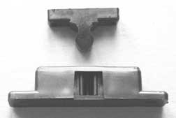 Various catches or fasteners have been used to hold
the grilles in place. The first ones to be used are in the ML-1C. They are
called a Spring-Action Box Catch number M-1219 sold by Selby Furniture Hardware
Company, Inc., 321 Rider Ave., Bronx, NY 10451.
Various catches or fasteners have been used to hold
the grilles in place. The first ones to be used are in the ML-1C. They are
called a Spring-Action Box Catch number M-1219 sold by Selby Furniture Hardware
Company, Inc., 321 Rider Ave., Bronx, NY 10451.
Selby describes these plastic catches as: "A positive location of strike in contained double spring action. Elongated holes for front to back adjustments. Black polyethylene standard. 2" long X 7/16" deep X 1/2" thick." On the bottom is molded "patt. app. 10262/66. Made in England. 1219."
Although the catches seem to work initially, repeated use causes some of them to fail. The plastic material is easily deformed. Many are replaced over the years. Today, unfortunately, they are no longer available, according to Selby. They are used in the ML-1C and ML-10C systems near each corner of the grille. In the ML-2C, ML2M, ML-4C, and ML-4M systems, the plastic catches are only used at the top of the grilles.
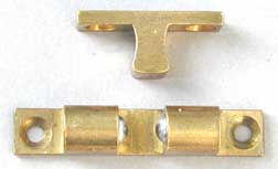 A different catch is used on the bottom of the ML-2C,
ML2M, ML-4C, and ML-4M grilles. This is called a Solid Brass Double-Ball catch.
It is much sturdier and does not damage easily. It is also made by Selby. It is
described as: "Adjustable tension double-spring double-ball catch for
positive closing action and secure holding. Extruded brass body and strikes
with chrome steel balls." The catch is identified as M-240A. Size is 1-15/16" X
3/8" X 7/16" high. To my knowledge, none of these have failed.
A different catch is used on the bottom of the ML-2C,
ML2M, ML-4C, and ML-4M grilles. This is called a Solid Brass Double-Ball catch.
It is much sturdier and does not damage easily. It is also made by Selby. It is
described as: "Adjustable tension double-spring double-ball catch for
positive closing action and secure holding. Extruded brass body and strikes
with chrome steel balls." The catch is identified as M-240A. Size is 1-15/16" X
3/8" X 7/16" high. To my knowledge, none of these have failed.
In later systems these brass catches were eliminated and two pins on the bottom of the grilles were inserted in holes in the base of the cabinet.
 Hinged grilles are used only in the XR-3, XR5, XR-6
and XR-7 systems. Half is attached and recessed in the cabinet and the other
half is in the grille.
Hinged grilles are used only in the XR-3, XR5, XR-6
and XR-7 systems. Half is attached and recessed in the cabinet and the other
half is in the grille.
They are made by Universal Industrial
Products Company, Inc., One Coreway Drive, Pioneer, Ohio 43554-0628. 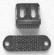 They are called the SOSS Invisible
Hinge and are number 203.
They are called the SOSS Invisible
Hinge and are number 203.
Each section is 1-3/4" high, 1/2" wide and requires a 3/4" deep recess. The hinges are located at the left side of the cabinet. They have worked very well and there have been no failures that I know of.
Catches made by 3M products keep the grilles closed. They are located on the right side of the cabinet at the top and bottom of the grille. The catches on the grille and on the cabinet are shaped like tiny mushrooms and interlock when pushed together. They don't appear to be in the current line of 3M fasteners. The bottom piece is 1-5/8" long and 1/2" wide. The top piece is 3/4" across and 1-7/8" high. These fasteners held very well—perhaps too well.
 In later systems, the grilles are held in place with
nylon catches in this case called fasteners and are made by Jet Press Limited,
Nunn Close, Huthwaite, Nottinghampshire, NG17 2HW, UK. These are called Treelok Fasteners.
In later systems, the grilles are held in place with
nylon catches in this case called fasteners and are made by Jet Press Limited,
Nunn Close, Huthwaite, Nottinghampshire, NG17 2HW, UK. These are called Treelok Fasteners.
They are described as follows: "Jet Press treelok Fasteners provide a neat and efficient method of securing access panels together. The socket and stud design allows easy opening of the required panel, such as an inspection cover, with a moderate level of pull out force."
The stud is 1/2" in diameter and 1/2" deep. The socket is 11/16" in diameter and 1/2" deep. The rounded U-shaped stud is compressed slightly when inserted in the socket until it reaches a slightly expanded area and then stays in place.
![]()
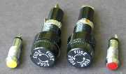
Before testing the system with audio signals, Check the fuses, if any, and replace blown ones with exact replacements. Use fast blowing fuses only. DO NOT USE SLO-BLO fuses. If part or all of the system does not play, further tests are needed.
Driver failure can be quickly located by using fm interstation hiss at a low power level. Listen at each speaker to verify if all the speakers are at least working. A low power level (1 to 5 watt sine wave sweep 20Hz to 20kHz can be used as a quick check for distortion. A driver with obvious distortion must be replaced.
To determine if a driver is dead, remove the driver and connect a 1-1/2 to 6 volt battery across the driver terminals. If no sound is heard, the driver must be replaced.
The crossover network must be inspected if a speaker element produces sound with the battery test but does not play when connected in the system. Check for bad connections, burned resistors, exploded capacitors, broken wires, etc.
Use only McIntosh replacement capacitors or equivalent capacitors having low effective series resistance (ESR).
Use RTV silicone rubber under replacement parts mounted on the crossover board. In addition to the solder connections, this insures a vibration free bond to the board.
A dot or red mark normally indicates the positive terminal of a driver. If the polarity of a driver is unknown, momentarily connect a 1-1/2 to 6 volt battery to the driver terminals. When the cone moves away from the magnet, it means the positive terminal of the battery is connected to the positive terminal of the speaker.
When installing a driver or crossover that covers a hole in the cabinet in the cabinet, care must be taken to insure a tight air seal. A foam gasket or soft foam tape is recommended. In some early speakers, a caulking material has been used to make the seal. This can be scraped off and replaced with foam. If you decide to use a caulking compound, use a material that doesn't harden, otherwise you may not be able to get the driver or crossover out again.
If a mid or woofer screw strips out in the wood of the cabinet, the driver can be rotated and new mounting holes drilled.
After the system is reassembled, it must be checked for air leaks. For the sealed systems, this can be done by driving the system with a 20Hz sine wave at 50 watts (20 volts). By listening around the speaker closely for hissing sounds, areas can be located that must be sealed. The system must also be swept from 20Hz to 700 Hz at 25 watts (14 volts) to insure there are no vibrations due to wires hitting the woofer cone, crossover, etc.
A seal is not required for the tweeters in the column systems XRT18, XRT20, XRT22, XRT25, XRT26 and XR290.
![]()
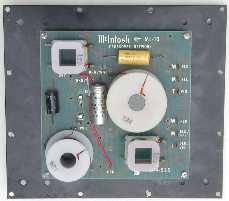
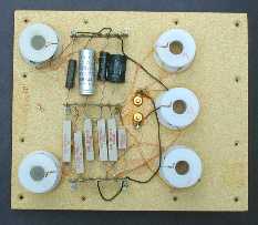 The first crossover networks were made in 1971 by
United Speaker Systems in East Orange, NJ. These are for the ML-1C. The board materials, parts
and layout were furnished by United. This followed the circuit I had designed.
Later, they were also made for the ML-2C, ML-2M, ML-4C and ML-4M.
The first crossover networks were made in 1971 by
United Speaker Systems in East Orange, NJ. These are for the ML-1C. The board materials, parts
and layout were furnished by United. This followed the circuit I had designed.
Later, they were also made for the ML-2C, ML-2M, ML-4C and ML-4M.
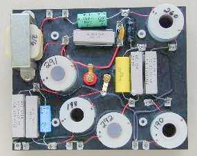
The crossovers are assembled on a wooden board 3/8" thick. Terminal strips are stapled to the board and the resistors and capacitors are glued in place between them. The leads are then soldered to the terminals. The coils are on nylon bobbins that are also glued and stapled in place. The board is 10-5/8" wide and 9" high. The terminals are gold plated. The mounting nuts and terminal pins can be seen near the center of the picture. The resistors can be seen near the bottom of the board.
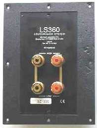
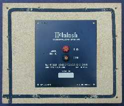 The other side of the board has a 6" X
5-1/2" steel plate with red and black binding posts and silk screened
information including a white area for the serial number to be stamped. Black
foam tape is added to the board just inside of the screw holes. The assembly
mounts from the inside of the cabinet and forms a tight seal. The board is held
in place with 12 wood screws. The cutout in early cabinets is round and about
4-3/4" in diameter. Later cabinets have a cutout 5-1/8" square. Both
cutouts have beveled edges.
The other side of the board has a 6" X
5-1/2" steel plate with red and black binding posts and silk screened
information including a white area for the serial number to be stamped. Black
foam tape is added to the board just inside of the screw holes. The assembly
mounts from the inside of the cabinet and forms a tight seal. The board is held
in place with 12 wood screws. The cutout in early cabinets is round and about
4-3/4" in diameter. Later cabinets have a cutout 5-1/8" square. Both
cutouts have beveled edges.
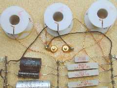 Wires with slip-on connectors are used from the
terminal strips to the driver terminals. Additional jumper wires are used to
complete the circuits. The coils all have #21 wire except for the woofer series
coil that has #19 wire. The board is stamped with a date but is too faint to
see in the picture. This board is dated DEC 16 1971. It
also has an inspection number 8 stamped on it. The coil values are sometimes
written by hand on the bobbins.
Wires with slip-on connectors are used from the
terminal strips to the driver terminals. Additional jumper wires are used to
complete the circuits. The coils all have #21 wire except for the woofer series
coil that has #19 wire. The board is stamped with a date but is too faint to
see in the picture. This board is dated DEC 16 1971. It
also has an inspection number 8 stamped on it. The coil values are sometimes
written by hand on the bobbins.
![]()
New Crossover Design--Second Generation
After a few years of use in customer homes, I found that a few of the earlier systems had been damaged. The ML systems had no protective devices such as fuses or circuit breakers. The fault is actually from the power amplifiers being driven into serious clipping. This is often because the amplifier has inadequate power output. Had a higher power amplifier been used, clipping would not have occurred and the system would not have been damaged. And, of course, this was before the days of McIntosh Power Guard. Had power Guard been incorporated then, even in the lower power amplifiers, these catastrophes would not have happened.
I learned that in one case the person had his ML-4's in the basement and had played them very loud so that he could hear them upstairs. Then there were several instances of parties where the amplifiers were grossly overdriven in an attempt to play them louder. The networks, mid domes and tweeters were damaged.
The woofers and 8" mids survived the clipping amplifiers but the associated crossovers didn't. In addition, these distorted signals are rich in harmonic content and the energy shifts up into the mid and high frequency region as well. After the mids and tweeters burned out, the systems continued to be driven. Then the associated crossover parts burned as well.
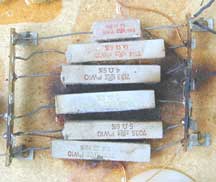 Although there were very few systems that suffered
damage, when it happened it was serious. The 10-watt power resistors had become
so hot that the red writing had turned brown or disappeared entirely. Portions
of the wood board under the resistors had turned to charcoal. Sometimes
resistors had exploded. The heat from some resistors had melted the
solder holding the resistor in place and it sometimes broke contact with the
solder lug. In addition, the electrolytic capacitors in the woofer circuits had
exploded and even the thick nylon bobbin for the crossover coils had melted and
sagged.
Although there were very few systems that suffered
damage, when it happened it was serious. The 10-watt power resistors had become
so hot that the red writing had turned brown or disappeared entirely. Portions
of the wood board under the resistors had turned to charcoal. Sometimes
resistors had exploded. The heat from some resistors had melted the
solder holding the resistor in place and it sometimes broke contact with the
solder lug. In addition, the electrolytic capacitors in the woofer circuits had
exploded and even the thick nylon bobbin for the crossover coils had melted and
sagged.
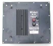 The solution was to redesign the crossover
construction and build it at McIntosh. This began in 1973 with the ML-10C
system. My crossover design includes a metal back plate that has the crossover
on one side and the connecting terminals, decal with serial number and heat
sink for the resistors on the other side. The assembly is mounted from the
inside of the cabinet and only the center portion can be seen through the
square hole in the cabinet. Caulking compound is placed around the cutout to
form a good seal to the cabinet. This assembly is for the McIntosh ML-10C
system. It is 9" wide and 8" high. The heat sink at the left of
center has 6 fins and is mounted to the plate with two screws.
The solution was to redesign the crossover
construction and build it at McIntosh. This began in 1973 with the ML-10C
system. My crossover design includes a metal back plate that has the crossover
on one side and the connecting terminals, decal with serial number and heat
sink for the resistors on the other side. The assembly is mounted from the
inside of the cabinet and only the center portion can be seen through the
square hole in the cabinet. Caulking compound is placed around the cutout to
form a good seal to the cabinet. This assembly is for the McIntosh ML-10C
system. It is 9" wide and 8" high. The heat sink at the left of
center has 6 fins and is mounted to the plate with two screws.
 On the backside, a fiberglass epoxy printed circuit
board is mounted on 5/8" stand off posts. The large coils are attached to
the board with RTV silicone rubber that holds them firmly in place. The square
coils have four solder lugs that attach to the PC board. The capacitors have
RTV under them to hold them in place and prevent vibration. The leads go into
holes in the board.
On the backside, a fiberglass epoxy printed circuit
board is mounted on 5/8" stand off posts. The large coils are attached to
the board with RTV silicone rubber that holds them firmly in place. The square
coils have four solder lugs that attach to the PC board. The capacitors have
RTV under them to hold them in place and prevent vibration. The leads go into
holes in the board.
The PC board is 6" by 6". Six lugs on the right side are for slip-on connectors. Silk screening on the board indicates the wire color: W for woofer, M for mid and T for tweeter.
 The resistors are mounted on a small plate underneath
the PC board. The leads are soldered to pins that are soldered to the foil side
of the board. Two pieces of fiberglass tubing are under the resistors. When the
PC board is assembled to the back plate, the resistors rest against the plate
at the same place where the heat sink is located on the other side. The unused
area of the PC board is coated to prevent solder from adhering to the copper
foil in places where it isn't needed.
The resistors are mounted on a small plate underneath
the PC board. The leads are soldered to pins that are soldered to the foil side
of the board. Two pieces of fiberglass tubing are under the resistors. When the
PC board is assembled to the back plate, the resistors rest against the plate
at the same place where the heat sink is located on the other side. The unused
area of the PC board is coated to prevent solder from adhering to the copper
foil in places where it isn't needed.
Originally, the new crossover design was to also incorporate a main system fuse and a tweeter fuse. I decided to supplement the fuses with two indicator lights. These were to be located on two rectangular plates mounted on the front panel of the system.
 A yellow light glows when the system is being driven
near maximum power handling. A red light glows when the tweeter fuse is blown.
Diodes and resistors protect the lamp circuits. The power for the lamps is
taken from the input signal to the speaker. The impedance of the lamp circuit
is more than 100 times the speaker impedance and has no effect on the
performance of the system. The light and fuse feature was never added to the ML
systems. The cabinets, however, had already been modified to accept the plates.
Blank plates were substituted. Wire jumpers were added to the PC boards to
bypass the circuits for the fuses and lights. The new systems were to be named
the ML-1D, ML-2D, ML-2N, ML-4D, ML-4N and ML-10D. See my ML-10D
page for more details.
A yellow light glows when the system is being driven
near maximum power handling. A red light glows when the tweeter fuse is blown.
Diodes and resistors protect the lamp circuits. The power for the lamps is
taken from the input signal to the speaker. The impedance of the lamp circuit
is more than 100 times the speaker impedance and has no effect on the
performance of the system. The light and fuse feature was never added to the ML
systems. The cabinets, however, had already been modified to accept the plates.
Blank plates were substituted. Wire jumpers were added to the PC boards to
bypass the circuits for the fuses and lights. The new systems were to be named
the ML-1D, ML-2D, ML-2N, ML-4D, ML-4N and ML-10D. See my ML-10D
page for more details.
Third Generation Design
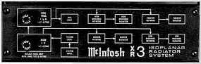 In 1976, Gordon Gow decided to come out with a new
line of systems instead of upgrading the ML systems. These became the XR3, XR5,
XR6 and XR7. They include the fast acting fuses and lights. In this design the
crossovers are accessible from the front of the cabinet near the top. They are
on printed circuit boards that slide into an aluminum box with plastic rails on
each side. Copper foil contacts on the board slide into a socket at the back of
the box. The front of the box is covered with a thick black aluminum extrusion.
A block circuit diagram is attached to it. The two fuse holders are mounted on
the left side.
In 1976, Gordon Gow decided to come out with a new
line of systems instead of upgrading the ML systems. These became the XR3, XR5,
XR6 and XR7. They include the fast acting fuses and lights. In this design the
crossovers are accessible from the front of the cabinet near the top. They are
on printed circuit boards that slide into an aluminum box with plastic rails on
each side. Copper foil contacts on the board slide into a socket at the back of
the box. The front of the box is covered with a thick black aluminum extrusion.
A block circuit diagram is attached to it. The two fuse holders are mounted on
the left side.
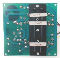
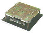
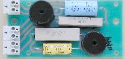
 Here's an XR5 crossover network. In this design, the
resistors are located on the top of the printed circuit board. A metal heat
sink is placed under them. The heat sinks are made from scrap chrome plated
steel that was used for the amplifiers, tuners etc. The square crossover coils
have a mounting pin in each corner are soldered to the PC board. The remaining
components are attached to the board with adhesive and the leads are soldered.
This keeps the parts from vibrating and making secondary noise. In my original
design and first production, RTV silicone adhesive is used to hold the parts in
place, including the large crossover coils. For a while, production used hot
melt but it was later found that hot melt would not hold adequately and RTV was
again used. Four spade lugs are used to make connections to the fuse holders.
Here's an XR5 crossover network. In this design, the
resistors are located on the top of the printed circuit board. A metal heat
sink is placed under them. The heat sinks are made from scrap chrome plated
steel that was used for the amplifiers, tuners etc. The square crossover coils
have a mounting pin in each corner are soldered to the PC board. The remaining
components are attached to the board with adhesive and the leads are soldered.
This keeps the parts from vibrating and making secondary noise. In my original
design and first production, RTV silicone adhesive is used to hold the parts in
place, including the large crossover coils. For a while, production used hot
melt but it was later found that hot melt would not hold adequately and RTV was
again used. Four spade lugs are used to make connections to the fuse holders.
The last 3 digits of the coil part number and the coil value are marked on the coil forms. The connections from the crossover can be seen at the top center of the board. A corner at the bottom left is cut out to allow space for the rear of the fuse holders. A large hole at the bottom in the center is for a plastic pull-tab to remove the crossover from the box. In practice, the contacts were so tight at the rear that the board often had to be levered out with a screw driver or pliers.
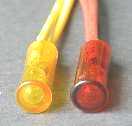 I located a company that makes yellow and red lights
that can be mounted flush with the cabinet surface. These are placed in the
bottom tray just below the grille and on the right side. I wrote the following
information for the owner's manual:
I located a company that makes yellow and red lights
that can be mounted flush with the cabinet surface. These are placed in the
bottom tray just below the grille and on the right side. I wrote the following
information for the owner's manual:
 "Yellow Light The yellow indicator light circuit
is connected directly across the input terminals. It will begin to be visible
only when the input power to the system approaches rated power. The brightness
of the light will fluctuate with the amplitude of the high power being fed to
the system. This light serves only as a warning indicator. It is completely
safe to operate the system under these conditions. The main fuse will blow if
the system is driven excessively hard. If the fuse does blow and the system is
still driven hard, the light will continue to fluctuate even though no sound
will be heard.
"Yellow Light The yellow indicator light circuit
is connected directly across the input terminals. It will begin to be visible
only when the input power to the system approaches rated power. The brightness
of the light will fluctuate with the amplitude of the high power being fed to
the system. This light serves only as a warning indicator. It is completely
safe to operate the system under these conditions. The main fuse will blow if
the system is driven excessively hard. If the fuse does blow and the system is
still driven hard, the light will continue to fluctuate even though no sound
will be heard.
Red Light The red indicator light is connected directly across the high frequency fuse. This light will be visible only when this fuse protecting the high frequency speakers has blown. The brightness of the light will fluctuate with the amount of high frequency signal still being fed to the system after this fuse has blown. A fluctuating red indicator light will be accompanied by a severe loss of high frequencies. Power will no longer be delivered to the upper midrange(s) and tweeters until the fuse is replaced."
In addition to fuse protection, a new feature incorporated into McIntosh amplifiers was the Power Guard circuit. This was an adaptation from my Popular Electronics magazine article about a volume compressor-expander that I wrote in 1962. It prevents the power amplifier from going into clipping and damaging the drivers
 The last system to use a printed circuit board in this
time period is the early version of the XRT20 made in 1979. This does not have
the plug-in feature. The circuit board is mounted on four metal standoff pieces
that are attached to a 1/8" thick hardened aluminum back plate. The back
plate also has the McIntosh label and fuses.
The last system to use a printed circuit board in this
time period is the early version of the XRT20 made in 1979. This does not have
the plug-in feature. The circuit board is mounted on four metal standoff pieces
that are attached to a 1/8" thick hardened aluminum back plate. The back
plate also has the McIntosh label and fuses.
A 55-watt power resistor can be seen that is attached to the aluminum plate.
Fourth Generation Design
Starting with the XR14 in 1979, the plug-in crossover feature is eliminated. Since adding the fuse protection, access to the crossover boards is rarely needed. In addition, a few contact problems have developed with the plug-in feature. The extra expense and resulting problems do not justify this arrangement.
 The new boards are made of 1/8" tempered
Masonite. All the components are hand wired, wrapped and soldered. Heat sinks
are still used under the resistors and all the components are attached with RTV
silicone adhesive. Dual solder lugs are riveted to the board for all the parts
connections. The boards are mounted inside the cabinet usually behind the
woofer. A large cutout in the rear of the cabinet allows room to display a
McIntosh label attached to the back of the board. This has the serial number
and other information. It also has the system connecting terminals that are
mounted on the board. The board in the picture is from an HT-1 system.
The new boards are made of 1/8" tempered
Masonite. All the components are hand wired, wrapped and soldered. Heat sinks
are still used under the resistors and all the components are attached with RTV
silicone adhesive. Dual solder lugs are riveted to the board for all the parts
connections. The boards are mounted inside the cabinet usually behind the
woofer. A large cutout in the rear of the cabinet allows room to display a
McIntosh label attached to the back of the board. This has the serial number
and other information. It also has the system connecting terminals that are
mounted on the board. The board in the picture is from an HT-1 system.
This construction is used for many years up to the mid 1990's when printed circuit boards are again used. The indicator lights were discontinued in about 1986 with the introduction of the XR1052 and the restyled version of the XRT18. Feedback from a dealer was that the lights made a customer "nervous." Gordon Gow decided not to use them any more.
Fuses Are Eliminated
Although the fuses work well and a package of extra fuses is supplied with each speaker system, changing them is still inconvenient. It can lead to installing the wrong fuse or not having any on hand to use at all. Of course this would defeat the purpose of having fuses to protect the drivers.
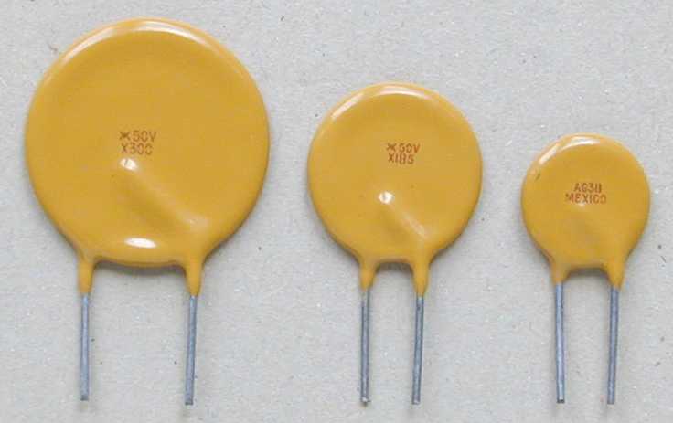 Fortunately new technology came along in 1990. I
decided to use bistable solid state current sensors. They look like ceramic
disc capacitors and come in a variety of sizes. These devices respond closely
to the heating characteristics that occur in driver voice coils. High
short-term currents won't cause them to trip unless the cumulative heating
effect over a period of time is exceeded. Excessive power causes the device to
switch from an extremely low resistance (typically 0.1 ohms) to practically an
open circuit. They can be reset by simply by turning down the volume for 5 to
10 seconds. This is automatic and no access is needed. They have worked very
well over the years. One sensor is in series with the entire system and a
second is in series with the tweeter crossover. I have bridged the tweeter
sensor with a resistor of high value so that if it does trip, the tweeter
output won't be entirely eliminated.
Fortunately new technology came along in 1990. I
decided to use bistable solid state current sensors. They look like ceramic
disc capacitors and come in a variety of sizes. These devices respond closely
to the heating characteristics that occur in driver voice coils. High
short-term currents won't cause them to trip unless the cumulative heating
effect over a period of time is exceeded. Excessive power causes the device to
switch from an extremely low resistance (typically 0.1 ohms) to practically an
open circuit. They can be reset by simply by turning down the volume for 5 to
10 seconds. This is automatic and no access is needed. They have worked very
well over the years. One sensor is in series with the entire system and a
second is in series with the tweeter crossover. I have bridged the tweeter
sensor with a resistor of high value so that if it does trip, the tweeter
output won't be entirely eliminated.
Early versions of the XR230 and XR240 have both fuses and sensors. The fuseholders and input connectors are on the back of the cabinet. In the XR250 and later versions of the XR230 and XR240, the input terminals are located underneath the cabinet. There are no fuses and no hole in the rear of the cabinet but the crossover is still located behind the woofer for easy access.
After I left McIntosh in late 1992, the SL-4, SL-6, LS-310, LS-330, LS-350, XRT24 and XRT25 systems for some reason have been designed and manufactured with no protection at all for the drivers. This is something I would never have done after all the experience I had gained. The HT-1, HT-4 and HT-4THX systems have sensor protection but only for the tweeters. At least the XRT26 and XR290 have them for woofers, mids and tweeters. The new Academy series of speakers also uses them.
Fifth Generation Design
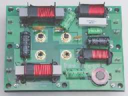 This crossover is used in the Academy LS360 that went
into production in 2001. This has a printed circuit board. Several laminated
bar coils are used. Four slip-on lugs are located at each side of the board for
connection to the drivers. Information is silk screened on the board such as
the part number, Mcintosh name and the wire colors that go to each connecting
lug.
This crossover is used in the Academy LS360 that went
into production in 2001. This has a printed circuit board. Several laminated
bar coils are used. Four slip-on lugs are located at each side of the board for
connection to the drivers. Information is silk screened on the board such as
the part number, Mcintosh name and the wire colors that go to each connecting
lug.
The crossover measures 6" x 8" and is attached to a steel back plate with eight screws and 1/2" plastic stand off insulators.
Eight large holes around the perimeter of the printed circuit board are large enough for a screw driver to get to screws that hold the steel plate to the inside of the cabinet. A large cutout in the rear of the cabinet allows room to display a McIntosh label attached to the back of the board. This has the serial number and other information.
 Four gold plated connecting terminals are 3/4" in
diameter and centers are 1-1/4" apart. Gold plated straps connect the two
sets of terminals. The straps can be removed for bi-amp operation. In this
mode, one amplifier can drive the woofers and a second amplifier can drive the
remainder of the system. The crossover network remains connected as part of the
system.
Four gold plated connecting terminals are 3/4" in
diameter and centers are 1-1/4" apart. Gold plated straps connect the two
sets of terminals. The straps can be removed for bi-amp operation. In this
mode, one amplifier can drive the woofers and a second amplifier can drive the
remainder of the system. The crossover network remains connected as part of the
system.
The whole assembly weighs 1300 grams or about 2.9 lbs. A foam gasket can be seen around the perimeter, which insures a good seal between the steel plate and the cabinet.
Car Audio Crossovers
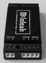 A different approach has been taken for the car audio
crossovers. Normally crossovers are located inside a speakers system and never
seen. Appearance is not supercritical. However, for car audio products they are
sold only with the drivers to be installed in a car system. The appearance
plays an important role here.
A different approach has been taken for the car audio
crossovers. Normally crossovers are located inside a speakers system and never
seen. Appearance is not supercritical. However, for car audio products they are
sold only with the drivers to be installed in a car system. The appearance
plays an important role here.
Other important design criteria are size and weight. There's not a lot of room in cars to hide things. The crossover must be as small as possible and weigh as little as possible. The weight is often a requirement of the car manufacturer, particularly for original equipment installations.
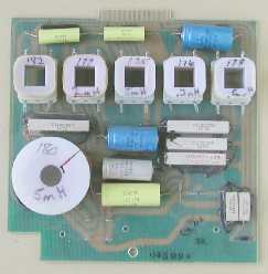
The crossover in the left picture is the MN493 that is used with the MSS471 and MSS472 speaker systems. These are two-way systems. The crossover is completely enclosed in a black plastic box. Two holes go through the box for mounting. Six ports are shown at the bottom of the picture. Connections are made by inserting a wire into the port. A screwdriver can be inserted in the hole above the port and the terminal tightened down. The terminals are gold plated.
 A printed circuit board is used. The coils are
unusually small and have round I shaped cores. The two wires are dressed out of
the bottom of the coil and go into holes in the board. The core is are attached
with RTV adhesive and the wires are soldered to the board underneath.
A printed circuit board is used. The coils are
unusually small and have round I shaped cores. The two wires are dressed out of
the bottom of the coil and go into holes in the board. The core is are attached
with RTV adhesive and the wires are soldered to the board underneath.
The box is 1-1/4" high, 5-1/4" wide and 2-3/4" deep. The whole assembly weighs 234 grams or about 8.3 ounces.
![]()
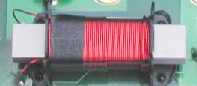
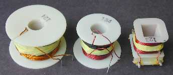 Many different crossover coils have been used over the
years. They were all made using a nylon bobbin. Inductance ranges from 0.05 mH
to 33 mH. Most of them were wound on the same coil winder that was used for the
McIntosh output transformers. A majority of the coils are attached to the
crossover board with RTV silicone adhesive that adheres to the nylon bobbin
very well. At one time production used hot melt glue but that was abandoned
when they found it didn't stick to the nylon. At one time printed circuit
boards were used for the speaker systems. For this type of assembly, square
bobbins were used for the smaller coils that had four solder pins, which held
the coils to the board.
Many different crossover coils have been used over the
years. They were all made using a nylon bobbin. Inductance ranges from 0.05 mH
to 33 mH. Most of them were wound on the same coil winder that was used for the
McIntosh output transformers. A majority of the coils are attached to the
crossover board with RTV silicone adhesive that adheres to the nylon bobbin
very well. At one time production used hot melt glue but that was abandoned
when they found it didn't stick to the nylon. At one time printed circuit
boards were used for the speaker systems. For this type of assembly, square
bobbins were used for the smaller coils that had four solder pins, which held
the coils to the board.
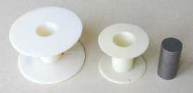 The larger bobbin is 2-1/4" in diameter. The
smaller bobbin is 1-1/2" in diameter. Both have a 5/8" hole in the
center and are 1-1/4" high.
The larger bobbin is 2-1/4" in diameter. The
smaller bobbin is 1-1/2" in diameter. Both have a 5/8" hole in the
center and are 1-1/4" high.
In some cases a high permeability iron core is used to increase the coil inductance. This reduces the size and the amount of copper wire needed for large inductances. This sintered core is dimensioned so that it will just fit inside the bobbin.
The core was selected to have very low distortion. Not all iron cores are the same. The iron cores used in some other brands of speaker systems introduce very significant distortion in the speaker output. The core shown above is described in detail in my article in Speaker Builder issue: six 1996 Page 44 [9 pages] titled Quality Issues in Iron Core Coils. Distortion is only 0.2% at 20 watts and remains below 1% at 600 watts. A few iron core coils made by other companies have distortion of 1% at 20 watts and 15% at 100 watts.
The copper wire size of the coils varies depending on the crossover network design. Added resistance is often needed in series with the coil for a particular design. Instead of using a resistor, the coil wire size is reduced to give proper resistance for that circuit. A further bonus is that the weight of copper is reduced as well. The wire size used in the McIntosh coils ranges from #18 wire to #28 wire.
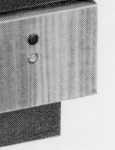
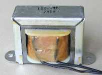 For the really big inductance values where very low DC
resistance is also needed, a special coil is used. This consists of a laminated
E core with a controlled air gap to the remaining laminated piece that
completes the inductive circuit. The wire portion is wound on a nylon bobbin
with a square hole in it. The bobbin fits on the center of the E. Two insulated
wires are attached to the coil and brought out. A U-shaped frame holds the
assembly together and the whole thing is dipped in varnish to keep the
laminations from vibrating. Distortion is even lower than the round core coils
and at powers up to 1000 watts. This coil is attached with two screws to the
crossover board.
For the really big inductance values where very low DC
resistance is also needed, a special coil is used. This consists of a laminated
E core with a controlled air gap to the remaining laminated piece that
completes the inductive circuit. The wire portion is wound on a nylon bobbin
with a square hole in it. The bobbin fits on the center of the E. Two insulated
wires are attached to the coil and brought out. A U-shaped frame holds the
assembly together and the whole thing is dipped in varnish to keep the
laminations from vibrating. Distortion is even lower than the round core coils
and at powers up to 1000 watts. This coil is attached with two screws to the
crossover board.
The coil is 2" high, 3-1/4' wide and 1-1/2" deep. It weighs 15 ounces. This type of coil is used in the ML-4 (late versions), XL1W, XRT18, XRT20, XRT22, XR1051, XR1052 and XR290.
 All of these coils are used for many years but recent
designs use a laminated bar for the core. The bar type is used in the new
Academy systems. The coil is held by a plastic form. Four mounting holes in the
form are used for mounting to the printed circuit board.
All of these coils are used for many years but recent
designs use a laminated bar for the core. The bar type is used in the new
Academy systems. The coil is held by a plastic form. Four mounting holes in the
form are used for mounting to the printed circuit board.
The coils for the car systems are not made by McIntosh. A much smaller round I shaped sintered core is used that has the turns wound directly on the core.
![]()
Woofer Cones
A wide variety of cone materials have been tried over the years. Each different material is claimed to have superior performance by the manufacturers. Some are made of paper, cloth impregnated with plastics or phenolic, Aluminum, titanium or other metals, polypropylene, polystyrene or other plastics, carbon fiber, Kevlar, and even paper made from the Sweet Daphne tree that grows only in Japan. There are even combination cones with a sandwich of various materials such as paper or aluminum. Remember the Leak sandwich speaker or the flat honeycomb diaphragm. Some are even made of solid Styrofoam. We have been led to believe that these materials are much better than paper. One of the reasons that plastic or metal cones have become widely used is for ease of manufacture. It’s a lot cheaper, less time consuming and there are fewer rejects when compared to the paper felting process.
Despite all of the new materials, paper cones still perform as good or better overall than most other materials. Paper has been used for speaker cones since the 1920’s. Of course, there are all kinds of paper and it depends on the kind of characteristics the designer is looking for. One of the better papers for woofer cones is based on Kapok. Kapok comes from a tree and is used as stuffing for pillows, mattresses, life saving equipment and insulation. These fibers are fine air-filled tubes and are impermeable to humidity. The fibers are very light and strong. The McIntosh woofer cones have been made with a blend of kapok for many years. However, this was changed for woofers made since 1992. Against my advice, polypropylene cones were used instead. Polypropylene does not keep a conical shape at lower frequencies and long excursions.
 Here’s a picture that I took of a kapok tree that is
growing along the Wallace River in Belize (Central
America). The trees lose all of their
leaves in the dry season. After the tree flowers, an ellipsoid fruit or pod is
produced that can be up to 6” long and 2-3/4” in diameter. It’s covered by
silky cotton-like fibers that are very lightweight. This is called kapok.
These fast growing trees are known to reach more than 150 feet in height and
can be up to 6 feet in diameter. The roots develop buttresses.
Here’s a picture that I took of a kapok tree that is
growing along the Wallace River in Belize (Central
America). The trees lose all of their
leaves in the dry season. After the tree flowers, an ellipsoid fruit or pod is
produced that can be up to 6” long and 2-3/4” in diameter. It’s covered by
silky cotton-like fibers that are very lightweight. This is called kapok.
These fast growing trees are known to reach more than 150 feet in height and
can be up to 6 feet in diameter. The roots develop buttresses.
![]()
For the next couple of years some design changes are put into effect. Some are still used today and others are not. The comments about these changes are my opinions based on engineering facts and do not include the reasoning for any marketing strategy that may have been involved.
New Driver Requirements
Instead of using soft dome tweeters, aluminum dome tweeters are used. The woofers and mid-ranges are changed to use cast aluminum baskets and a "shiny look" coating is added to the cones. Rubber surrounds are used in place of polyether ones. Impedance is changed to 4 ohms.
Aluminum Dome Tweeters
Aluminum domes typically have a pronounced resonance around 25kHz. This may contribute to the characteristic sound of the aluminum material. Although we don't hear that high, lower frequency subharmonics can excite this resonance. Interaction with program material can then cause intermodulation distortion products that can be audible. Also see Stereophile May 1994 pages 113 and 115 that reviews the McIntosh Home Theater speakers.
Heavier Moving Mass
The addition of the “wet look” laminate to the cone and the new heavy rubber surrounds reduce the output of a typical 12” woofer by a little over 3 dB. This means twice the power is needed to achieve the same listening level as the earlier designs. Reducing the impedance of the new systems to 4 ohms is a way to make up for the loss in efficiency.
Impedance of Home Systems is Changed To 4 Ohms
All systems manufactured prior to 1993 were 8 ohms and had an industry standard sensitivity rating of 1 watt into 8 ohms at a distance of 1 meter. All systems made after this date are 4 ohms and have sensitivity rating of 2.83 volts into 4 ohms. This turns out to be 2 watts into 4 ohms, making them appear to have greater sensitivity. To convert to a 1-watt level, subtract 3 dB from the rated sensitivity. For example: the LS350 is a 4-ohm system rated at 89dB for 2.83 volts. This converts to the industry standard rating of 86dB for 1 watt at a distance of 1 meter.
Generally, a 4 ohm speaker will play louder on a direct coupled amplifier than an 8 ohm speaker simply because it draws twice the power with the lower impedance. A few companies have used this strategy for many years. The idea is that when a simple switch arrangement is used in a dealer store to compare different speakers, the louder one is supposed to be the one that gets the sales—and this does help.
Reducing the speaker impedance to 4 ohms does not improve the accuracy of the speaker, reduce distortion or make any other improvements. However, it does create problems for the customer. It means that the customer must purchase heavier speaker wire to maintain the same low losses compared to the earlier 8-ohm speakers. The total DC resistance of the wire must now be less than 0.4 ohms instead of 0.8 ohms. It also requires better connectors at the speaker and amplifier terminals to make the contact resistance even lower.
Most direct-coupled amplifiers deliver higher power to lower impedance loads. The exception is McIntosh amplifiers with Autoformers that can deliver the same power to a variety of load impedances. The new 4-ohm impedance means that the drivers will be subject to even higher power than previous designs. Excessive power to a system can cause higher distortion, crossover failure and even demagnetization of the driver magnets. The best designs that handle higher power are ones that use multiple drivers for each frequency range. This way the power to individual drivers is a lot less compared to a single driver covering the same frequency range. The best of these designs have floor to ceiling columns such as the XRT20, XRT22 and XR290. Low distortion can be maintained even with high power input to the system.
Maximum Power Ratings Changed
Perhaps as a consequence of higher power being delivered to the systems, the claimed power ratings were arbitrarily increased. All earlier systems were conservatively rated for continuous music listening. My favorite test was to subject a speaker to 8-hour sessions of continuous rock music. An amplifier corresponding to the rated speaker power is driven with the Power Guard indicator red lighting about 50% of the time. Although the power ratings for the new systems have higher numbers, they should be considered as a rating only for occasional short duration peaks and not for continuous music or steady tones. In comparison, this means that the power Guard indicator on a bigger amplifier should flash red very infrequently or not at all.
Frequency Response Tolerance Added
A response tolerance is introduced to be plus or minus so many dB. This tolerance is based on measurements made in an anechoic (reflection free) environment. While I was at McIntosh, I never specified this, as it can be misleading for the customer. A typical home environment is very different and can drastically alter the response amplitude. Frequencies below 1000Hz and particularly below 250Hz are influenced by the speaker location, room dimensions and construction. This can completely defeat a claim of plus or minus 1 or 2 dB. In some rooms response peaks and dips can be as much as 15 dB. Even mid-range and high frequency response can be altered by reflecting objects within a few feet of the speakers, including the floor and ceiling. The advertised tolerance is no indication of what the actual response will be in your home.
|
About This Site |
||
|
|
|
More text and pictures about McIntosh will be added as my research continues. Any comments, corrections, or additions are welcome. |
|
|
Created
by Roger Russell |
|