A Zobel for the
IDS-25
by Roger Russell
This
page is copyrighted
No portion of this site may be reproduced in whole or in part
without written permission of the author.
Power factor
I was always interested in AC power transmission and some of the problems that are encountered by a power company. To efficiently deliver useful power to customers requires an understanding of the kind of load the equipment places on the power connection. Here are a few basics in alternating current. The effectiveness of power transmission is determined by the relationship of the voltage and current delivered to the load. It reminds me of the basic course in electronics at school. I remember the words ELI the ICE man. This means that for an inductor L, the voltage E leads the current I. For a capacitor C, the current I leads the voltage E.
Typical loads found in power transmission
|
Resistive |
Incandescent lamps, heating elements in stoves or furnaces |
|
Inductive
|
Motors and relay coils |
|
Capacitive |
Start and run capacitors or power factor correction capacitors. |
|
Inductive |
Capacitive |
Resistive |
|
|
|
|
|
|
|
|
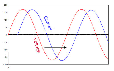
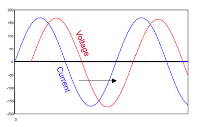
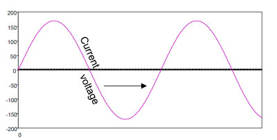
For a power company, AC power is used most efficiently when the current is aligned with the voltage and is shown in the resistive picture. However, most equipment is inductive and tends to draw current with a delay, misaligning it with the voltage as shown in the inductive picture above. Because of the inductive reactance that is introduced, the apparent power is then higher than the useful or true power supplied to the load.
|
|
|
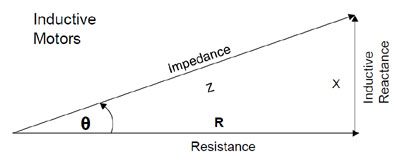
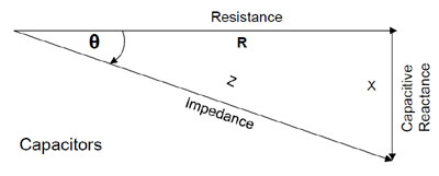
The relationship can be seen for motors and capacitors when illustrated in a polar diagram.
Power factor is a way of measuring how efficiently electrical power is being used within a customer's electrical system. These components are referred to as True Power (watts), Apparent Power (VA) and Reactive Power (VAR).
|
|
|
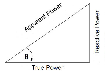
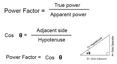
The cosine of the angle between the apparent power and true power is a measure of the power factor. True power is volts times amps times the power factor. When the current and voltage occur at the same time, the power factor is unity and is an optimum load. The greater the reactive power, the lower the power factor.
To realign the current and voltage for an inductive load, a bank of appropriate capacitors are inserted at the load. The higher apparent power delivered by the power company is then reduced to the true power. The cancellation of inductive reactance reduces excessive current and cost to the power company. This can also be thought of as a zobel used to compensate for an inductive element. A zobel is also known as a Boucherot cell. Most power systems operate at 50Hz or 60 Hz but amplifiers and speakers operate through the whole audio spectrum and even beyond. In a similar way, loudspeaker systems are loads for the power amplifier. Zobels can also be used to cancel the reactive part of a loudspeaker load as seen by the amplifier.
IDS-25 loudspeaker and Zobels
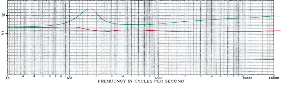
The green curve of impedance versus frequency shows a typical IDS-25 system impedance. It is unique because it has no crossovers and is very close to that of a single driver in a test box. This is because the series-parallel connection of the 25 identical drivers comes out to the same impedance as a single driver. Impedance is 6.3 ohms at 20Hz and rises to a 13 ohm resonant peak at 180Hz If we were to look at the phase relationship between voltage and current, we would see the voltage leading the current before the impedance peak. Beyond the impedance peak, reactance is capacitive and the current leads the voltage. Rising impedance at the higher frequencies is caused by the inductance of the voice coil winding. The impedance is 7.1 ohms in the area of 500Hz and rises to 9.5 ohms at 20kHz. Unlike some wide-range drivers, the impedance at the higher frequencies would be greater if it were not for the copper shorting ring used in the voice coil gap.
Adding the Zobels
The
red curve is the result of neutralizing the reactive components in the system.
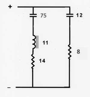
A series RLC circuit (zobel) having the opposite
impedance characteristic is placed across the input terminals of the system.
This cancels out the impedance peak. A series RC (zobel)
is also placed across the system terminals to cancel out the rising impedance
at higher frequencies. The overall system impedance is now essentially reduced
to a resistive value ranging from 5.6 to 7.1 ohms while the driver DC
resistance remains at 6.3 ohms. The system effectively presents a true power
load to the amplifier.
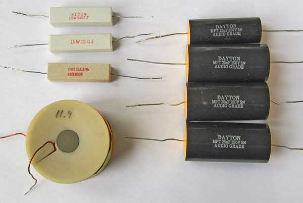
Here are the components I used to
create the entire IDS zobel. All of the components
are 5% tolerance)
 The capacitors are
low loss polycarbonate. Electrolytic capacitors are not used because they have
high ESR (effective series resistance) and make the series resonant circuit too
broad. For the first circuit, I used three 25mfd capacitors in parallel to make
a total of 75mfd. The coil is made with many turns of #19 magnet wire
supplemented with a low distortion iron core to provide a total of 11 mH inductance. There were no 14-ohm resistors in the parts
box so I used 12 ohms plus 2 ohms in series. The second circuit compensates for
the rising high frequency impedance. I use a 12mfd capacitor in series with an
8-ohm 15-watt resistor.
The capacitors are
low loss polycarbonate. Electrolytic capacitors are not used because they have
high ESR (effective series resistance) and make the series resonant circuit too
broad. For the first circuit, I used three 25mfd capacitors in parallel to make
a total of 75mfd. The coil is made with many turns of #19 magnet wire
supplemented with a low distortion iron core to provide a total of 11 mH inductance. There were no 14-ohm resistors in the parts
box so I used 12 ohms plus 2 ohms in series. The second circuit compensates for
the rising high frequency impedance. I use a 12mfd capacitor in series with an
8-ohm 15-watt resistor.
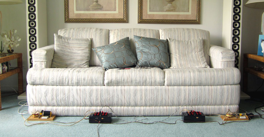
To
make a comparison, I use my remote relay switching boxes (master and slave) The
zobel boards are placed at either end of the couch
and can be switched in or out at the system input terminals. A remote button is
used to control the relay switching. I use a McIntosh MC252 power amplifier to
drive the prototype systems.
One
of the first questions is what happens to the response of the system after this
adjustment? Little change, if any, should be expected by eliminating the
reactive parts with the zobels. Measurements show
that the acoustic output of the system decreases overall by less than 0.5dB
through the whole frequency range. This means that if the system was driven by 1
watt before the change, then 1.06 watts is needed for the same listening level
and can be considered negligible.
Can
all of this be heard? The relay box provides an instant A-B comparison. After
playing a wide variety of music, no listening difference can be heard. Then I
resort to using random phase pink noise and only then can I hear a very slight
difference in the overall level. To compensate for the difference when the zobels are not connected, I reduce the level slightly. Then
there is no listening difference even with random noise. In fact, for
full-range drivers like this, zobels are not needed
at all. In this case, zobels may be a benefit for
some users who might like to know the zobels are
connected and doing the right thing for their power amplifier. This said,
however, for special amplifiers that tend toward current source behavior, a zobel like this one can preserve the original IDS-25
performance. A resistive load can be a benefit for them. High capacitance
speaker wire can even create load problems for some of these amplifiers.
For
some amplifiers that have several output impedance taps from an output
transformer or autoformer, a 6-ohm impedance with the
zobels is right in the middle between 4 and 8 ohms.
6- ohm taps are normally not provided. The standard “safe” answer would be to
connect to the 4 ohm tap. The reason is that the lower impedance on an 8 ohm
tap could otherwise cause extra heating of the amplifier by drawing extra
current. However, the 6 ohms presented with the zobels
draws only true power and none of the reactive power that would draw extra
current from the amplifier. The 8-ohm tap is still safe in that respect.
Multi-way Systems
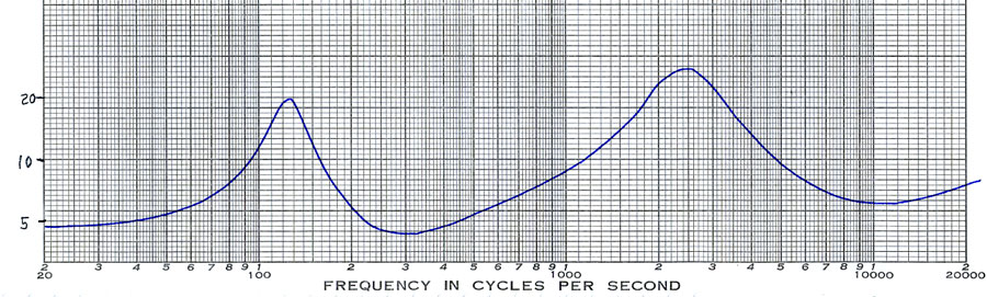
The
above impedance curve is for a small 2-way speaker system that is rated at 4
ohms. In this system there are several reactive elements that hide the true
resistance of the system. The lowest impedance is 4.7 ohms in the area of 20Hz,
4.0 ohms at 300Hz and 5.9 ohms at 11kHz. The maximum impedance is 20 ohms at
125Hz and 28 ohms at 2500Hz. An ideal load for an amplifier would be a constant
resistance of 4 ohms versus frequency. Although zobels
can be placed at the input terminals of the IDS-25 system, a multi-way system
such as this 2-way system is more complicated. Zobels
must be connected directly across each driver. This will reduce each driver to
essentially a true resistive load. However, the crossover components might need
adjustment if previous calculations were using a different driver impedance. Consequently,
this adjustment could make an audible difference.
|
About This Site |
||
|
|
Created
by Roger Russell |
|