Jefferson Electric Clock
Troubleshooting, Restoration and Improvements
By Roger Russell
These
pages are copyrighted
No portion of this site may be reproduced in whole or in part
without written permission of the author.
![]()
What's on this page?
Glass Replacement
Includes instructions for attaching or replacing the glass.
Also includes information on replacing the glass with clear acrylic.
Clear acrylic is shatter resistant, lighter,
reduces motor heating and wear and is optically superior.
Ordering information for clear acrylic discs is provided
Golden Minute, Golden Helm and Golden View
![]()
Here
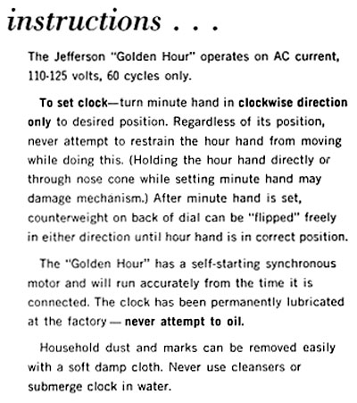
is a copy of a portion of the instruction book that came with the Golden Hour
that I bought from Jefferson about 1980. It replaces the earlier cartoon
manual.
Please note that you should never attempt to oil the clock.
![]()
Golden Hour, Exciting Hour, Golden Helm, Golden Minute and Golden View Clocks
After many years of use, these clocks can run fast, slow or not at all. There can be several different causes.
(1) The clock may run fast. A common failure is caused by the glass becoming completely detached from the large outer gear ring. Replacement glass can be found at Timesavers. The concept for why the clock could run fast was a little difficult to visualize at first. When the glass is free, it rolls inside the outer gear ring, which is driven by the motor. Since the glass diameter is slightly less than the inside of the gear ring, the glass then rotates faster than the ring. The minute hand attached to the glass then appears to advance relative to the motor driven ring and the clock is seen to run fast.
(2) The clock may run slow or not at all. The clock motor may be running but the output gear from the gearbox doesn't turn or turns intermittently. One of the gears inside the motor gearbox may be stripped. You can either rebuild the motor gearbox as described below, or simply replace the motor/gearbox assembly.
Alternately, the motor output gear has been worn by the outer steel ring gear that's attached to the glass and only contacts it some of the time or not at all. A new motor assembly may be required or you might try some surgery described in the improvements section.
![]()
In a few rare cases, when the glass has broken, the dial ring or even the gear ring may have been distorted out of round. Although this is highly unlikely, it could happen. The roundness can be easily determined after removing the dial ring assembly from the base. The gear ring should turn freely in the dial ring. If it does not, the rings will need to be made round again before reassembling the clock.
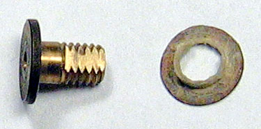
Another possible cause for the clock to run fast is in the hour hand assembly. The smaller diameter portion of the main stem shown above protrudes from the hour hand assembly. After adding the fiber washer, the main stem goes through the center hole from the back of the glass. The unthreaded portion of the main stem is a little longer than the glass thickness. The difference is taken up with a fiber washer located between the wide stop at the left end of the main stem and the back of the glass. The threaded portion is used to tighten the cone nut at the front of the glass. The flat portion on either side of the thread matches the slot in the minute hand.
Over the years, this fiber washer can become thinner and allow the cone nut to bottom on the unthreaded portion without being adequately tight. This allows the entire hand assembly to roll inside the glass hole as the dial turns, making the time appear to go a little faster.
The above picture shows the fiber washer in place on the hour hand assembly. The solution is to add a thin metal washer under the fiber washer and allow the cone nut to be once again hand tightened without bottoming.
![]()
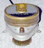 What is referred to as the "motor" actually
consists of a motor and gearbox assembly all in one package. The gearbox
reduces the high rpm and low torque of the motor down to a lower rpm and higher
torque. The original motors in the Golden Hour and Golden Minute clocks have a
synchronous motor made by The International Register Company, 15 South Throop
Street, Chicago, IL U.S.A. This was the company's main location from the early
to mid 1900's. The company was renamed in the early 1970's to Intermatic
Incorporated. The motors are 240 rpm and have a stall torque of 60 in/oz at the
output gear. They are rated at 115V, 60C, 2.5W. They are UL and CSA approved.
What is referred to as the "motor" actually
consists of a motor and gearbox assembly all in one package. The gearbox
reduces the high rpm and low torque of the motor down to a lower rpm and higher
torque. The original motors in the Golden Hour and Golden Minute clocks have a
synchronous motor made by The International Register Company, 15 South Throop
Street, Chicago, IL U.S.A. This was the company's main location from the early
to mid 1900's. The company was renamed in the early 1970's to Intermatic
Incorporated. The motors are 240 rpm and have a stall torque of 60 in/oz at the
output gear. They are rated at 115V, 60C, 2.5W. They are UL and CSA approved.
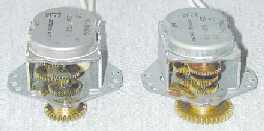 In 1977, Mr. E. J. Sticka, Manager of Advertising and
Sales Promotion, informed me that they were having manufacturing problems with
the Intermatic motors.
In 1977, Mr. E. J. Sticka, Manager of Advertising and
Sales Promotion, informed me that they were having manufacturing problems with
the Intermatic motors.
Different motors were supplied for a while around that time. They have exposed reduction gear assemblies. The motor at the right side of the picture is a Golden Minute replacement motor sent to me by Jefferson in 1977. It is numbered WG-1060. It's rated at 125V, 60C, 3W. The output gear has 36 teeth and a CW rotation.
The motor at the left came from an Exciting Hour clock and is numbered WG-1040-1. It's rated at 1/6 rpm, 125V, 60C, 3W. The output gear has 27 teeth and a CW rotation. Unfortunately, there is no date in the clock or on the motor. Both motors have the Litton logo on the back as well as saying Jefferson Electric. There is no indication of UL or CSA approval.
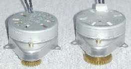 Today's replacement motor assemblies are made by
Mallory. They have thicker and more rugged internal nylon gears. The motors are
600 rpm and have a stall torque of 400 in/oz at the output gear. The left
assembly has a 27 tooth output gear for the Golden Hour and Exciting Hour. The
right assembly has a 36 tooth output gear for the Golden minute, Golden Helm
and Golden vision. Golden Hour motors, glass, gear rings and other parts are
available for the Golden Hour from Timesavers.
Motors for converting the Golden Hour to 220-240V 50Hz operation are also
available from them.
Today's replacement motor assemblies are made by
Mallory. They have thicker and more rugged internal nylon gears. The motors are
600 rpm and have a stall torque of 400 in/oz at the output gear. The left
assembly has a 27 tooth output gear for the Golden Hour and Exciting Hour. The
right assembly has a 36 tooth output gear for the Golden minute, Golden Helm
and Golden vision. Golden Hour motors, glass, gear rings and other parts are
available for the Golden Hour from Timesavers.
Motors for converting the Golden Hour to 220-240V 50Hz operation are also
available from them.
![]()
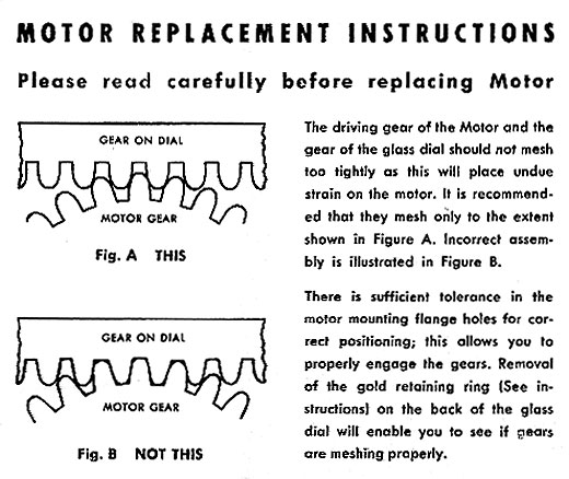
The following instructions came with a Jefferson replacement "motor" for the Golden Hour:
![]()
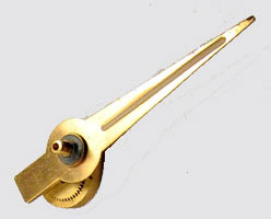
These parts are from a Golden Hour clock dated 2-17-61. None of the parts are magnetic. They all appear to be made of brass except for the fiber washers and what may be a beryllium-bronze tension washer.
The cone nut can be removed by holding the counterweight/hour hand assembly at the rear of the glass and unscrewing the cone nut at the front of the glass.
The pieces are arranged in the order that they are assembled. The glass/gear ring assembly is not shown. They are as follows starting from the right:
|
|
1. Cone Nut |
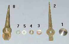
When reassembling the hands on the glass face, orient the hour hand and counterweight as it is shown in (8). Place the tension washer so the outer rim faces the minute hand. The indented portion of the minute hand must be at the rear and match the appearance of the indented hour hand. Orient both hands at the 12 o'clock position and screw the cone nut back in place.
The hour hand assembly (8) can be taken apart further by pushing a pin out of the rear of the counterweight.
|
|
9. Hour hand and single gear |
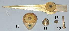
The hour hand subassembly (9) has four parts including a brass bushing that is press fitted at each end to keep them all rigidly together. At the large end of the hour hand is a counterweight that is different from the main counterweight. This keeps the hour hand in proper position relative to the minute hand. Attached to that is a 48 tooth gear.
The main counterweight subassembly (10) consists of 3 parts, the counterweight, pin and a double gear. The pin is press fitted into the counterweight and holds the gear in place. The large portion of the gear has 45 teeth and the small portion has 12 teeth.
The intermediate gear (12) has 15 teeth
The pin (13) has three different diameters that match the pieces that fit on it. The pin diameter for the counterweight is smaller than the hole in the counterweight to allow it to turn freely. The diameter for the small intermediate gear and the hollow post is an interference fit that must be pressed back into place when reassembled.
![]()
Improving Some Early Mystery clocks
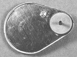
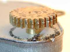 This motor assembly has been removed from a 1953
Golden Hour. The photo clearly shows how the brass motor output gear has worn against
the steel gear ring that's attached to the glass. A circle of brass particles
has accumulated under the gear.
This motor assembly has been removed from a 1953
Golden Hour. The photo clearly shows how the brass motor output gear has worn against
the steel gear ring that's attached to the glass. A circle of brass particles
has accumulated under the gear.
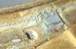
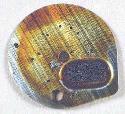
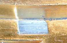 The weight of the assembly of glass, hands and gear
ring is 193 grams, or about 6.8 ounces. This entire weight rests on two raised
areas of the cast outer ring. Each raised area (shown at the right) is about
.300" by .175". Small metal pieces from the ring casting can be seen
nearby. In some clocks this area has been completely worn away and the outer
ring rests against an even larger area. In addition, there are three leaf
springs that press against the front of the gear ring.
The weight of the assembly of glass, hands and gear
ring is 193 grams, or about 6.8 ounces. This entire weight rests on two raised
areas of the cast outer ring. Each raised area (shown at the right) is about
.300" by .175". Small metal pieces from the ring casting can be seen
nearby. In some clocks this area has been completely worn away and the outer
ring rests against an even larger area. In addition, there are three leaf
springs that press against the front of the gear ring.
The overall friction force is high and the motor must work hard to turn the glass. It's tempting to put oil or grease on the outer ring to reduce friction but this will only pick up and accumulate dust and dirt that will eventually make things worse.
 About this time I came across some Teflon tape that
has adhesive on one side. A piece of tape about 7/32" wide and about
5" long can be placed around the bottom portion of the frame. The tape is
.006" thick. I thoroughly cleaned out the area with a Q-tip and alcohol so
the tape would stick well. Also, cut out the area of tape where the motor gear
meets the ring gear. If other spots around the frame show wear, the tape should
be extended to cover them as well. Sometimes the dial ring is out of round and
should be carefully bent back to near round before reassembling the clock.
About this time I came across some Teflon tape that
has adhesive on one side. A piece of tape about 7/32" wide and about
5" long can be placed around the bottom portion of the frame. The tape is
.006" thick. I thoroughly cleaned out the area with a Q-tip and alcohol so
the tape would stick well. Also, cut out the area of tape where the motor gear
meets the ring gear. If other spots around the frame show wear, the tape should
be extended to cover them as well. Sometimes the dial ring is out of round and
should be carefully bent back to near round before reassembling the clock.
There is usually a fair amount of vertical play between the gear ring and the inside of the dial ring. If the motor gear is badly worn, 4 layers of .006" thick tape would shift the contact area of the gear ring up to a new area on the brass motor gear. This would be like replacing the old gear.
Although this modification has been in use for only a short time, I hope wear can be reduced and the motor may run cooler than before. The ease of turning the glass assembly by hand is much improved from what it was. This technique can very likely be applied to the Golden Minute, Golden helm and Golden View.
Jefferson made improvements in later Golden Hours
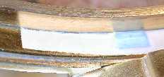
 Earlier Golden Hours have two raised cast areas in the
outer ring for the glass dial assembly to slide on. My 1984 Golden Hour has two
gray plastic bearing surfaces instead. These are about .235" by
.180". The material appears to be nylon that offers less frictional force.
Powder can be seen from wear of the nylon. The hole next to the nylon is for
one of two screws that hold the outer ring to the base of the clock. Part of
the base is in the lower right of the picture. This bearing surface is at 28
minutes on the dial.
Earlier Golden Hours have two raised cast areas in the
outer ring for the glass dial assembly to slide on. My 1984 Golden Hour has two
gray plastic bearing surfaces instead. These are about .235" by
.180". The material appears to be nylon that offers less frictional force.
Powder can be seen from wear of the nylon. The hole next to the nylon is for
one of two screws that hold the outer ring to the base of the clock. Part of
the base is in the lower right of the picture. This bearing surface is at 28
minutes on the dial.
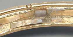 The second nylon bearing is mounted off to the left
side of the dial at about 43 minutes. Apparently it was thought that the motor
would push the glass dial assembly in this direction and it would be where the
bearing surface would work best. Gray powder can again be seen. One of the leaf
springs can be seen below the nylon bearing.
The second nylon bearing is mounted off to the left
side of the dial at about 43 minutes. Apparently it was thought that the motor
would push the glass dial assembly in this direction and it would be where the
bearing surface would work best. Gray powder can again be seen. One of the leaf
springs can be seen below the nylon bearing.
Nylon bearing surfaces have been found on Golden Hours as far back as 1961. The exact date of the change is not known. An Exciting Hour has been found that also has the nylon but there's no date in the clock.
![]()
Older clock motor assemblies get noisy and/or the internal gears slip, causing the clock to be slow or not run at all. After many years of service, the oil and grease fail to lubricate. This causes wear and even destruction of the gears. After opening an older gearbox, it may look like it's still well lubricated, but it isn't.
In the case of noisy motor assemblies, a simple but thorough cleaning and lubricating of the gears in the gearbox will restore the motor assemblies to quiet operation. The problem is to carefully open the seal around the gearbox. New motor assemblies have four tabs that are bent over the gearbox cover to hold it in place. These can be bent out and the gearbox opened. Older covers are sealed, often with a red adhesive, which needs to be softened with solvent, such as MEK.
A few covers are soldered in place and are a real challenge to open. The entire cover must be brought to a temperature to soften all the solder at the same time. I have not been successful with a soldering iron, even a high wattage one, but a propane torch will work if used carefully. This sort of desperate measure is worth pursuing when the motor runs but the output gear doesn't turn. I often feel, in this case, that there's nothing to lose.
I scraped all the solder that I could get off with a knife. Then, I used the torch intermittently for no more than 10 seconds total. I put a pair of needle nose pliers under the output gear as I heated the cover and applied a slight lifting pressure. This was enough to loosen the cover and it did not significantly heat the motor or gear box. There was a fiber paper directly under the cover of the gearbox and it bubbled slightly, but was not really damaged. Be sure the gearbox is vented so it won't explode when heated to several hundred degrees.
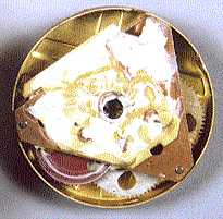
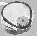
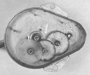 This motor gearbox is from a Haddon Golden Vision
clock that I had just opened. The date on the clock is Nov 1955. The clock
didn't run at all and the insides of the gearbox didn't look promising. The oil
had dried like a coat of varnish on all the gears and on the inside of the box.
There were also small pieces of dirt spread around, particularly under the
gears. I have used a black & white picture for better clarity. There are 4
gears in the picture; three large ones and one small one that is attached to
the motor shaft. There is one gear that remained attached to the cover and is
not shown. The gear at the left of the group is 0.64" in diameter and is
made of nylon. Beneath it, on the same subassembly, is a metal gear that is
0.090" diameter. The nylon portion is 0.032" thick and the metal
bottom portion is 0.057" thick.
This motor gearbox is from a Haddon Golden Vision
clock that I had just opened. The date on the clock is Nov 1955. The clock
didn't run at all and the insides of the gearbox didn't look promising. The oil
had dried like a coat of varnish on all the gears and on the inside of the box.
There were also small pieces of dirt spread around, particularly under the
gears. I have used a black & white picture for better clarity. There are 4
gears in the picture; three large ones and one small one that is attached to
the motor shaft. There is one gear that remained attached to the cover and is
not shown. The gear at the left of the group is 0.64" in diameter and is
made of nylon. Beneath it, on the same subassembly, is a metal gear that is
0.090" diameter. The nylon portion is 0.032" thick and the metal
bottom portion is 0.057" thick.
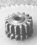 When I pulled this gear out and turned it over, I
found that a section of the metal cogs at the bottom had been worn away. This
is why the clock no longer ran and is the source of the "dirt" that
came from the worn away section. A metal gear to the right of the nylon gear,
in the above picture, is 0.024" thick and a slot this high had worn into
the bottom gear.
When I pulled this gear out and turned it over, I
found that a section of the metal cogs at the bottom had been worn away. This
is why the clock no longer ran and is the source of the "dirt" that
came from the worn away section. A metal gear to the right of the nylon gear,
in the above picture, is 0.024" thick and a slot this high had worn into
the bottom gear.
Instead of trying to replace this gear subassembly, if a replacement could ever be found, I decided to "cheat". Since the height of the damaged surface was only 0.024" and the total height available was 0.057", I found that an 0.025" thick washer placed under the left gear would raise the subassembly up and make the gear next to it contact a new section of the lower gear. The small motor output gear that drove the nylon gear, was high enough to still make proper contact with it. Now this gear was effectively restored to like new condition. I did this same procedure with the motor from a Jefferson Golden Minute clock in 1973, and it still runs today.
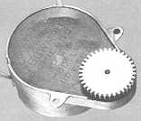
 This particular motor has an unusual lubricating
system. The shafts that hold the gears go to a plate that is similar to the shape
of the gearbox cover. It has holes in it for the shafts. When the plate is
turned over and placed against the cover, oil can be trapped in between the two
surfaces and held by capillary action. There's even an oval reservoir pad to
hold more oil. This ensures there will be adequate lubricating oil for a long
time. The old oil can be seen as a yellowish brown color. It was like molasses.
This particular motor has an unusual lubricating
system. The shafts that hold the gears go to a plate that is similar to the shape
of the gearbox cover. It has holes in it for the shafts. When the plate is
turned over and placed against the cover, oil can be trapped in between the two
surfaces and held by capillary action. There's even an oval reservoir pad to
hold more oil. This ensures there will be adequate lubricating oil for a long
time. The old oil can be seen as a yellowish brown color. It was like molasses.
 There's even a depression and hole in the cover to add
more oil from the outside. This can be seen as the small round area just to the
left of the remaining gear.
There's even a depression and hole in the cover to add
more oil from the outside. This can be seen as the small round area just to the
left of the remaining gear.
An ultrasonic cleaner is used to scrub tiny watch parts. I don't feel that this extreme is needed for these relatively large parts, but the cleaner the better. After cleaning, a small amount of grease can be put on the teeth of the gears. A small amount of light oil can be put on the shafts that contact the gears. I used it very sparingly and applied it with a fine applicator.
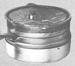
 This is what I found when I first opened the gearbox
of a Jefferson 500. White grease covered the thin brass plate. The brass plate
is removable. It creates a similar oil reservoir with the thicker plate under
it that has holes in it. The gears can be cleaned and lubricated in a similar
fashion.
This is what I found when I first opened the gearbox
of a Jefferson 500. White grease covered the thin brass plate. The brass plate
is removable. It creates a similar oil reservoir with the thicker plate under
it that has holes in it. The gears can be cleaned and lubricated in a similar
fashion.
I resealed the gearboxes with ordinary household cement or sometimes RTV silicone adhesive.
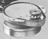
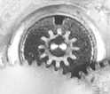 My best advice on servicing the motor portion of the
assembly is to let an expert work on it. In my experience motors themselves
don't usually fail, only the lubrication does. So cleaning and lubricating the
shaft of the motor is the only restoration I have done. One end is in the
gearbox, and has a small gear attached to it, shown in the center of the
picture. The other end is hard to get at under the flywheel. Care must be taken
not to bend the flywheel. It's almost impossible to bend it back so it won't
wobble.
My best advice on servicing the motor portion of the
assembly is to let an expert work on it. In my experience motors themselves
don't usually fail, only the lubrication does. So cleaning and lubricating the
shaft of the motor is the only restoration I have done. One end is in the
gearbox, and has a small gear attached to it, shown in the center of the
picture. The other end is hard to get at under the flywheel. Care must be taken
not to bend the flywheel. It's almost impossible to bend it back so it won't
wobble.
![]()
1961 Motor Descriptions
Jefferson
replacement motors have been described in the 1961 clock repair catalog No. 107
The E. & J. Swigart Co., P. O. Box 298, Merchants Bldg., 34 West Sixth
Street, Cincinnati 2, Ohio
|
|
Golden Hour 580-800 motor $5.25 |
|
|
Golden Helm 580-810 motor $5.48 |
|
|
Suspense 580-840 motor $5.48 |
|
|
Lady Marion 110-850 motor $5.91 |
|
|
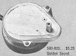
Golden Secret 580-820 motor $5.25 |
|
|
Electric battery clocks 580-700 set 2 batteries $2.27 |
As
described in the S. Larose, Inc. Catalog 1981
Jefferson part numbers and some motor specs. These motors are now obsolete.
Golden Hour 580-800
International WB5080 is interchangeable with 075-80-800. 27 tooth gear.
Golden Helm, Golden
Minute, Golden View 580-810
Golden Secret 580-820 1/60th RPM with 3/8" output shaft
Suspense 580-840 Int. Reg. W-3070 motor with sprocket gear
Contemporaire WB-990 Int. Reg. motor, CMR-2 Int. Reg. motor
movement assenbly
500, Lady
Marion 110-850 Hansen 9847 motor 1 RPM
Thanks to Jonas Clark-Elliot for the Larose catalog information.
|
About This Site |
||
|
|
More text and pictures about Jefferson will be added as my research continues. Any comments, corrections, or additions are welcome. |
|
|
|
|
All
contents are copyrighted |