The Origin of
by Roger Russell
These
pages are copyrighted
No portion of this site may be reproduced in whole or in part
without written permission of the author.
|
|
||||
|
The Dutch Secret |
The Golden Hour |
|
The Magic |
|
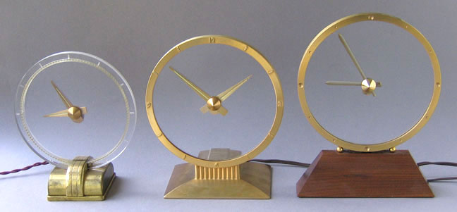
The history begins with the
three clocks shown above.
These clocks, including some of the Jefferson Electric clocks, are based on patents awarded in the 1940's to Leendert Prins. The patents are No. 2,248,195, RE22640, and No. 2,642,713. The Dutch Secret was the first invention of Leendert Prins. The name Etalage and Etalage Reclame is on a few of his other designs. Etalage Reclame is French and means something like dramatically effective display.
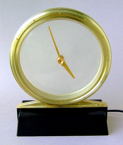
The clock in the center is
the Golden Hour and was made by Jefferson Electric in
The clock at the right is the Magic Crystal. It was made by the Etalage Reclame Corporation in New York City. This is the clock that is described in the Prins patent and not the Golden Hour. Radium paint is not used on this clock. The 110 volt motor is mounted vertically and protrudes from the rear of the clock. The ring and hand assembly are gold plated. The base is solid walnut. There is a more detailed description of this clock and other Prins designs on my Etalage page.
![]()
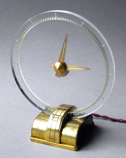
The Dutch Secret
Pictures
and descriptions of this clock are from my article published in the
NAWCC Bulletin (National Association of Watch and Clock Collectors) October
2004 Page 600 [6 pages]
It was made by Nederlandsche
Uuwerkfabrieken (NUFA) in
 A catalog advertisement is shown at the left. The ad, which was
originally in Dutch, translates to read as follows: "Invisible propulsion
by a self-starting synchronous motor (220-240 Volt, 50 periods, 3 watt). The
gilded hands are placed on a transparent plastic dial. A lamp fitted in the
base illuminates the hour indicators. Height 21 cm, Dial 17 cm." The clock
sold for 81 guilders or about $40.00.
A catalog advertisement is shown at the left. The ad, which was
originally in Dutch, translates to read as follows: "Invisible propulsion
by a self-starting synchronous motor (220-240 Volt, 50 periods, 3 watt). The
gilded hands are placed on a transparent plastic dial. A lamp fitted in the
base illuminates the hour indicators. Height 21 cm, Dial 17 cm." The clock
sold for 81 guilders or about $40.00.
It appears to be made of brass and transparent Plexiglas. The outer ring is 6-7/8" in diameter and 7/16" thick. It has oval hour positions that have an indented frosted surface. The marks at 3, 6, 9, and 12 o'clock are 0.130" X 0.255" and are 0.070" deep. The other hours are 0.080" X 0.215" wide and are 0.045" deep. A unique feature is the use of a small light hidden in the base. When the clock is plugged in, the ring illuminates and the hour marks can be clearly seen in dim light. There is no switch to turn the light on or off. Each hand has a line of radium paint along the center that also glows. The words “Made in Holland” are at the bottom of the ring. Weight of the clock is 550 grams or about 1.2 lbs.
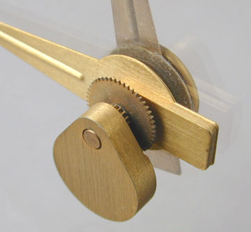 The picture at the right shows the hand assembly from the back of the
clock. The minute hand is mounted on the front of the plastic disc. It is held
by friction and can be moved to set the correct minutes. It is 2-13/16"
long and 3/8" wide at the base. The hour hand and gear assembly are
located behind the disc. The hour hand is 2-1/2" long and 3/8" wide at
the base.
The picture at the right shows the hand assembly from the back of the
clock. The minute hand is mounted on the front of the plastic disc. It is held
by friction and can be moved to set the correct minutes. It is 2-13/16"
long and 3/8" wide at the base. The hour hand and gear assembly are
located behind the disc. The hour hand is 2-1/2" long and 3/8" wide at
the base.
A shaft attached to the center of the disc has gears connected to the counterweight and hour hand. The gears reduce rotation so that one revolution of the disc advances the hour hand by one hour. The hour hand assembly can turn freely. The counterweight always stays in a vertical position and provides a fixed position needed to drive other gears that advance the hour hand. A small counterweight of metal is attached to the rear portion of the hour hand. It is the same shape and can be seen behind the main counterweight near the bottom of the picture. It serves to hold the hour hand in proper position relative to the minute hand.
The correct hours can be set by rotating the entire assembly one revolution in either direction for each hour. An indented line along the length of both hands contains radium paint. This is radioactive material. Although it may only glow faintly today, the radium is still active with a half life of 1600 years. Exposure to light is not necessary. The radiation intensity at one foot averages 0.03 mR/hr and is harmless. Even up close, at the point of contact, the combined radiation from both hands is only 2.1 mR/hr. Radium paint is no longer used in making watches and clocks.
 The base is 1-13/16" high, 3-1/4" wide and 3-1/2" deep.
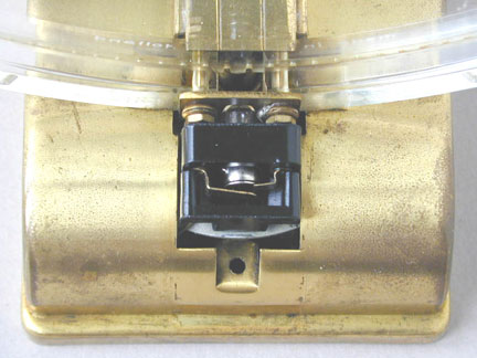
The top of the base has removable covers at the front and rear. The front
center cover has been removed in Figure 4 by removing a screw underneath the
base. Access can then be gained to the Bakelite lamp module. The module can
then be unplugged from the base to replace the lamp.
The base is 1-13/16" high, 3-1/4" wide and 3-1/2" deep.
The top of the base has removable covers at the front and rear. The front
center cover has been removed in Figure 4 by removing a screw underneath the
base. Access can then be gained to the Bakelite lamp module. The module can
then be unplugged from the base to replace the lamp.
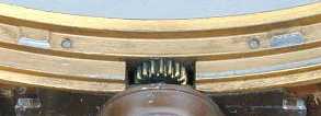
The filament of the incandescent lamp is positioned under the plastic dial ring. The two contact arms for the base of the lamp can be seen in the picture. The lamp is about the size of a T 1-3/4 bulb. It is a #6828 6 Volt 0.6 watt lamp and is no longer listed in the catalogs. It mounts similarly to a bayonet-style base and can be removed with a slight twist. The module plugs into the two brass pins on the main clock body. The pins are actually the ends of the screws that hold the plastic outer ring to the base of the clock. They also provide a power connection for the lamp.
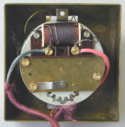
What is most interesting about this arrangement is where the 6 volts come from because the line voltage is 220 to 240 volts. There is a separate winding on the motor coil to provide this voltage and the winding is electrically isolated from the rest of the motor winding. The red and black wires are from the power line. The two small black wires go to the motor coil and two smaller wires go to the lamp module socket. Of course, a separate lamp winding was easily added in manufacture to the older motor coil but is not possible in more modern clock motor designs.
The two screws that hold the two base top covers also hold the bottom cover in place. When the bottom cover is removed, the motor and wiring are exposed as shown in Figure 8. The motor assembly is welded to the base. Although reduction gears can be seen between the circular motor mounting plate and the upper part of the base, I made no attempt to take this apart.
 The plastic dial ring is held in place with the two brass screws
mentioned earlier. Two red insulating shoulder washers can be seen where the
two screws pass through.
The plastic dial ring is held in place with the two brass screws
mentioned earlier. Two red insulating shoulder washers can be seen where the
two screws pass through.
In the center of the picture, the output gear from the motor can be seen. This is a brass cylinder that has four prongs that rotate. They mesh with the slots in the plastic disc holding the hands. There are 120 slots around the perimeter of the disc. The cylinder rotates at 30 revolutions per hour or 1/2 revolution per minute and this advances the disc one revolution per hour.
Although there is no date on the clock, there are several characteristics about it that indicate it is old and may have been made in the 1940's. The line cord is made of two insulated cloth-covered wires twisted together like much of the electrical equipment made in the 1920's and 1930's, such as Jefferson Electric toy transformers as well as toasters, lamps, etc. The disc and ring could be made of Plexiglas that was commonly available at that time. Plexiglas was introduced in 1936 by Rohm & Haas in both the United States and Germany. It was used extensively in airplanes in WWII. Radium paint is used on the hour and minute hands. The motor is typical of older electric clocks of the 1940's, such as the Rex Cole clock
![]()

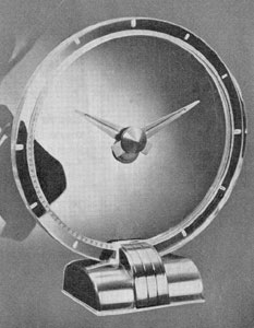
The Magic Crystal
 There is no model number or name indicated on this
clock. However, an advertisement refers to the clock as the Magic Crystal
Clock. A picture from the ad is shown at the right.
There is no model number or name indicated on this
clock. However, an advertisement refers to the clock as the Magic Crystal
Clock. A picture from the ad is shown at the right.
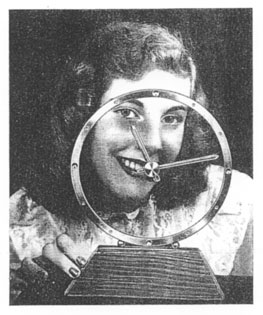
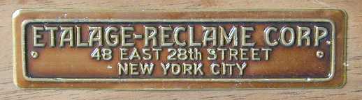 The nameplate on the bottom says Etalage-Reclame
Corporation, 48 East 28th Street, New York City. Etalage and Reclame are French
words that mean something like dramatically-effective display. Prins and his
daughter, shown in the picture at the right, assembled these clocks and the
earlier Etalage MagiClocks at their New York address.
The nameplate on the bottom says Etalage-Reclame
Corporation, 48 East 28th Street, New York City. Etalage and Reclame are French
words that mean something like dramatically-effective display. Prins and his
daughter, shown in the picture at the right, assembled these clocks and the
earlier Etalage MagiClocks at their New York address.
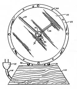 The clock could be thought of as an improved version
of earlier designs and a closer similarity to the first Jefferson clock. A
patent number RE 22640 is stamped in ink on the bottom of the wood base. This
is a reissue of patent number 2,248,195 on May 1, 1945. Application number
645,998 was filed on February 7, 1946 but it was abandoned. Application for a
new patent, serial number 101,510, was made in France on September 10, 1948 and
in the United States on June 27, 1949. On June 23, 1953 the patent number
2,642,713 was issued to Leendert Prins. After Jefferson bought the patent, this
number appears on several clocks such as the Golden Hour, Golden Minute
and Golden Helm clocks. The patent describes the clock in great detail
with 3 pages of illustrations. The round dial, glass and hand assembly is
mounted on a wooden base. The motor is mounted vertically and protrudes from
the rear of the clock. It has advantages over the earlier Prins patent. A
sketch from the patent is shown at the left.
The clock could be thought of as an improved version
of earlier designs and a closer similarity to the first Jefferson clock. A
patent number RE 22640 is stamped in ink on the bottom of the wood base. This
is a reissue of patent number 2,248,195 on May 1, 1945. Application number
645,998 was filed on February 7, 1946 but it was abandoned. Application for a
new patent, serial number 101,510, was made in France on September 10, 1948 and
in the United States on June 27, 1949. On June 23, 1953 the patent number
2,642,713 was issued to Leendert Prins. After Jefferson bought the patent, this
number appears on several clocks such as the Golden Hour, Golden Minute
and Golden Helm clocks. The patent describes the clock in great detail
with 3 pages of illustrations. The round dial, glass and hand assembly is
mounted on a wooden base. The motor is mounted vertically and protrudes from
the rear of the clock. It has advantages over the earlier Prins patent. A
sketch from the patent is shown at the left.
The clock is 9-7/8" high, 9-1/2" wide and 2-1/4" deep. Weight is 2 lbs. The lacquered solid walnut base is 7-1/2" wide, 2-1/4" high and 1-3/4" deep. The front and back of the wood is angled in at about 15 degrees. The sides are angled at 60 degrees. There are four 1/4" diameter brown felt pads on the bottom in the corners. The outer ring appears to be gold plated. It has rounded depressions about 1/16" deep and 1/4" in diameter to indicate the hours of 3, 6, 9 and 12 o'clock. The remaining hours have rounded depressions about 1/32" deep and 1/8" in diameter. A retaining ring holds the glass disk in the frame. Three small lugs are equally spaced around the rear of the frame. The retaining ring may be resiliently snapped into position to hold the disk.
The clock incorporates a single transparent disc. A shaft passes through the center of the glass. The minute hand is The hand can be easily turned to set the desired minutes. The rest of the assembly is located behind the glass. A shaft attached to the center of the disc has gears connected to the counterweight and hour hand. The gears reduce rotation so that one revolution of the disc advances the hour hand by one hour. The hour hand assembly can turn freely. The counterweight always stays in a vertical position and provides a fixed position needed to drive other gears that advance the hour hand. A small counterweight of metal is attached to the rear portion of the hour hand. It is the same shape and can be seen behind the main counterweight near the bottom of the picture. It serves to hold the hour hand in proper position relative to the minute hand. It is improved over the two-disc MagiClock for ease of setting the hours and minutes independently.
 The minute hand is held to the front of the glass by spring washers and
a cone nut. It is held by by friction so that it can be easily turned to
set to the desired minutes. The hour hand and gear assembly are located behind
the glass. A shaft passes through the center of the glass to the hour hand
assembly. A pear-shaped counterweight always stays in a vertical location from
gravity. It provides a fixed position needed to drive the gears that advance
the hour hand as the glass turns.
The minute hand is held to the front of the glass by spring washers and
a cone nut. It is held by by friction so that it can be easily turned to
set to the desired minutes. The hour hand and gear assembly are located behind
the glass. A shaft passes through the center of the glass to the hour hand
assembly. A pear-shaped counterweight always stays in a vertical location from
gravity. It provides a fixed position needed to drive the gears that advance
the hour hand as the glass turns.
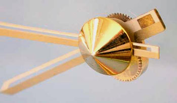
 The picture shows the rear of the hands and the pear shaped
counterweight assembly. There's also a counterweight at the end of the hour
hand and can be seen near the top left of the picture. It serves to hold the
hour hand in proper position relative to the minute hand. The hour and minute
hands are about 3/16" wide. They have a slot about .038" wide for
most of their length. The wide portion is gold colored and the thinner portion
is light beige. The back of the hands is also light beige. Radium paint is not
used on this clock and there is no illumination.
The picture shows the rear of the hands and the pear shaped
counterweight assembly. There's also a counterweight at the end of the hour
hand and can be seen near the top left of the picture. It serves to hold the
hour hand in proper position relative to the minute hand. The hour and minute
hands are about 3/16" wide. They have a slot about .038" wide for
most of their length. The wide portion is gold colored and the thinner portion
is light beige. The back of the hands is also light beige. Radium paint is not
used on this clock and there is no illumination.
 The clock is powered by a synchronous motor made by Haydon Mfg. Co,
Torrington, Conn. It's rated at 110V--60C and 2.3W. The output gear is 1 RPM. A
60:1 reduction results in the clock face turning at the required 1/60 rpm, or
one revolution per hour. The motor is mounted in a metal housing 2-1/2"
wide and 2-1/4" high that extends into the wooden base. The assembly is
painted dark brown. The numbers 8/48 on the motor indicate that the motor was
made in August of 1948 and the clock may have also been made in 1948. A second
clock has been found with a motor date of December 1949.
The clock is powered by a synchronous motor made by Haydon Mfg. Co,
Torrington, Conn. It's rated at 110V--60C and 2.3W. The output gear is 1 RPM. A
60:1 reduction results in the clock face turning at the required 1/60 rpm, or
one revolution per hour. The motor is mounted in a metal housing 2-1/2"
wide and 2-1/4" high that extends into the wooden base. The assembly is
painted dark brown. The numbers 8/48 on the motor indicate that the motor was
made in August of 1948 and the clock may have also been made in 1948. A second
clock has been found with a motor date of December 1949.
Jefferson made the first Golden Hour clock on December 2, 1949 after the patent rights were purchased from Prins. The Magic Crystal clock does tend to be a little tipsy as most of the weight is at the top and the base is not deep enough to keep it steady. In comparison, the Golden Hour is very stable and has no tendency to tip over.
One clock I have seen had an embossed label pasted on the bottom. Although the front part of the label had been peeled off the embossing could still be read. It says Tourneau, Importers of Watches, Madison Avenue, New York. This may have been the dealer that originally sold the clock back in the late 40's.
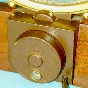
On the Inside
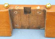 The square metal housing around the motor is made of
steel. It is held in place by four metal tabs. These must be bent in order to
get the housing off. In one clock I have seen the tabs broken off, probably
from repeated bending. The motor is mounted on a metal casting and is attached
to the base with three wood screws. The indent in the wood in the center is
where an intermediate gear fits. When the wood screws are removed the motor,
casting and ring assembly can be removed from the base.
The square metal housing around the motor is made of
steel. It is held in place by four metal tabs. These must be bent in order to
get the housing off. In one clock I have seen the tabs broken off, probably
from repeated bending. The motor is mounted on a metal casting and is attached
to the base with three wood screws. The indent in the wood in the center is
where an intermediate gear fits. When the wood screws are removed the motor,
casting and ring assembly can be removed from the base.
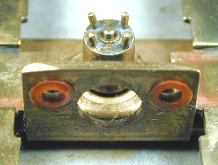
 The two decorative brass balls are held with two
threaded pieces that have been inserted into the wood base. This is all in
accordance with the patent description. The two flat head machine screws that
hold the casting to the outer ring can be seen in the picture below and to the
right. The view is from the front of the clock.
The two decorative brass balls are held with two
threaded pieces that have been inserted into the wood base. This is all in
accordance with the patent description. The two flat head machine screws that
hold the casting to the outer ring can be seen in the picture below and to the
right. The view is from the front of the clock.
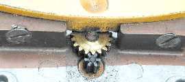 The motor output gear has 6 teeth and runs at 1 RPM.
It meshes with a brass intermediate gear that has 18 teeth and this makes a gear
reduction of 3 to 1.
The motor output gear has 6 teeth and runs at 1 RPM.
It meshes with a brass intermediate gear that has 18 teeth and this makes a gear
reduction of 3 to 1.
The intermediate gear meshes with the outer ring gear that has 360 teeth. This is a reduction of 20 to 1. The total reduction is 60 to 1 and the outer gear rotates at the required one revolution per hour.
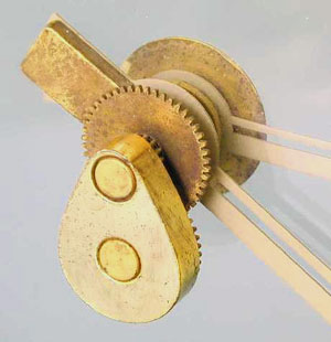
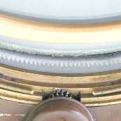 The picture at the left shows some of the parts of the
dial ring assembly spread apart. This view is from the rear. It consists of a
gold colored rear cover shown at the top. The rear cover is held in place by 3
small tabs that are part of the ring casting. Behind and below it is the outer
gear ring with the glass that is glued to it. The teeth of the outer ring are
triangular much like a saw blade. The ring is made of steel. Below that is the
cast ring showing several steps. The intermediate brass gear can just be seen
above the motor gearbox at the bottom of the picture.
The picture at the left shows some of the parts of the
dial ring assembly spread apart. This view is from the rear. It consists of a
gold colored rear cover shown at the top. The rear cover is held in place by 3
small tabs that are part of the ring casting. Behind and below it is the outer
gear ring with the glass that is glued to it. The teeth of the outer ring are
triangular much like a saw blade. The ring is made of steel. Below that is the
cast ring showing several steps. The intermediate brass gear can just be seen
above the motor gearbox at the bottom of the picture.
On either side of the intermediate gear, the ends of a circular split retainer ring can be seen. This circular retainer is shown the way it fits in one of the steps. It's made of brass wire that's 0.073" in diameter. It goes between the outer gear ring and the cover and serves to keep the outer gear ring and glass assembly in place.
 Two raised areas are on the inside of the ring. This
is where the weight of the glass/hand assembly rests. The assembly weighs 191
grams or about 6.7 ounces. The wear is not equal for the two tabs indicating
that the retainer ring is probably not centering the gear ring from front to
back as well as it should have.
Two raised areas are on the inside of the ring. This
is where the weight of the glass/hand assembly rests. The assembly weighs 191
grams or about 6.7 ounces. The wear is not equal for the two tabs indicating
that the retainer ring is probably not centering the gear ring from front to
back as well as it should have.
![]()
Alternate MagiClock Design
![]()
The original Prins design was modified by Warren Ferguson, an electrical engineer at Jefferson and became the Golden Hour. This was the beginning of the clock division for Jefferson Electric. The design was based on the Prins patent, however, a mystery remains as to how anyone at Jefferson Electric first learned of the clock and the patent. I have heard from several sources that in the late 1940's, the wife of the owner of Jefferson Electric found an interesting clock while on vacation in the Netherlands. The husband thought the idea was very novel and brought it back to the USA. This led to the patent purchase and clock redesign. It may have been the Dutch Secret that they saw.
|
The Jefferson Golden Secret
|
|
|
|
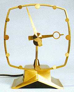
The Golden Secret clock has the name "holland" stamped in small letters on the top of the frame. This clock may have also been made by Nederlandsche Uuwerkfabrieken and sold by Jefferson in the USA. The clock has no glass and the hands are driven by a flexible shaft in a hollow curved tube. The motor is in the base. See my Golden Secret page for a more detailed description. |
![]()
|
About This Site |
||
|
|
More text and pictures about Jefferson will be added as my research continues. Any comments, corrections, or additions are welcome. |
|
|
|
|
Created
by Roger Russell |