|
Welcome to Roger Russell's |
||
|
|
|
|
These
pages are copyrighted.
No portion of this site may be reproduced in whole or in part
without written permission of the author.
![]()
What's On This Page?
|
Introduction |
Pages of Other Transformers from a 1928 Catalog with Pictures.
Jefferson Oil Burner Transformers
Jefferson Gaseous Tube Sign Transformers
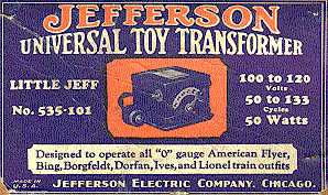
Jefferson Universal Toy Transformers
![]()
Besides making clocks, Jefferson also made many different kinds of transformers including toy (train) type, bell, radio replacement, oil burner ignition, control, luminous tube sign, door bell, signal, auto and double wound. The Toy Transformers could also be used for Christmas tree lights. In addition to transformers, Jefferson also made outlet and switch boxes, fuses, cutout bases and clips, and metal clad mercury switches.
It might seem strange that electrical technology was so far advanced for the 1910's and 1920's. Knowledge about coil properties, metallurgy, insulating materials, etc. was commonly known. The materials may not have been as sophisticated as what we have today, but the principles were the same and the products worked very well.
Nikola Tesla was influential in standardizing the frequency of power distribution systems to 60 cycles in the USA. Tesla based this frequency on the way we tell time. A frequency of 25 cycles had been common in some areas of the United States and Canada in the late 1920's to the early 1930's. It was used because power apparatus, such as synchronous converters and alternating-current commutator motors, work better at this lower frequency. However, at 25 cycles the flicker of lamps can be seen and is objectionable. The advantage of the higher frequency is that transformers require less iron and copper making them less expensive and lighter in weight.
Some of the older Jefferson transformers were for use with 25/40 cycle currents. Others were rated at 50/133 cycles. Fortunately, a 25/40-cycle transformer can be used safely with today's 60-cycle house current. About 1965, the term for line frequency was changed from cycles to hertz (Hz).
![]()
![]()
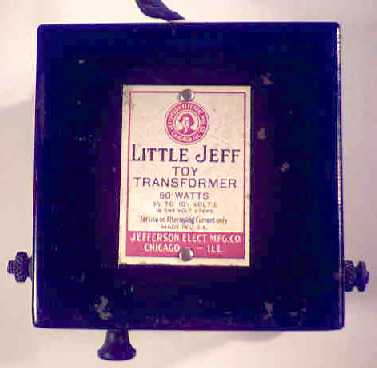
LITTLE
JEFF--No. 535-101
50 watts capacity
 Jefferson
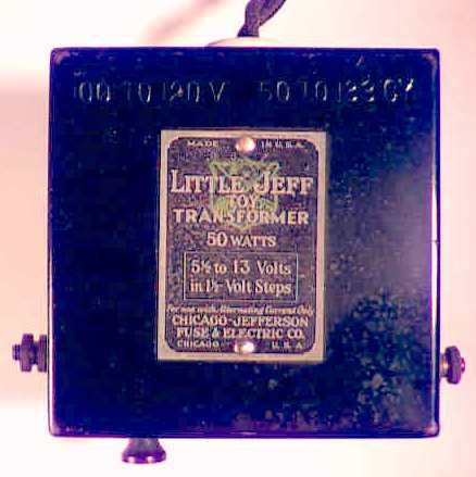
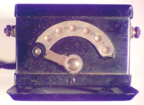
Little Jeff Toy Transformer. This transformer delivers six secondary voltages
ranging from 5-1/2 to 13 volts in 1-1/2 volt steps. It is recommended for all
Bing, Ives and Lionel "O" gauge outfits except No. 268 outfit.
Jefferson
Little Jeff Toy Transformer. This transformer delivers six secondary voltages
ranging from 5-1/2 to 13 volts in 1-1/2 volt steps. It is recommended for all
Bing, Ives and Lionel "O" gauge outfits except No. 268 outfit.
A green emblem is painted under the name Little Jeff. The 7 position circular slider is at the front of the transformer. The line cord is made of two separate wires with black cloth on the outside. These are twisted together and exit the transformer case through a porcelain grommet that says Jefferson 100 1. The other end has an old style plastic two-prong plug
The transformer case is fastened to a square dish shaped bottom plate at four raised points near the corners. The note stamped in the top says "100 to 120V. 50 to 133 CY."
The transformer case size is 2-3/8"H, 3-1/2"W and 3-1/2"D. Size including terminals, plate and slider knob is 2-7/8"H, 4-3/8"W and 4-1/4"D. Chicago-Jefferson Fuse & Electric Co. Chicago U.S.A.
![]()
LITTLE
JEFF--No. 535-111
50 watts capacity
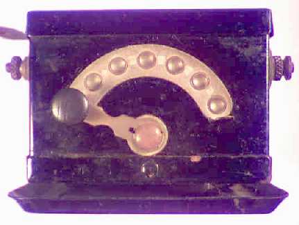 This is a
second version of the Little Jeff for other trains. It has the same wattage but
the voltage is from 5-1/2 to 10-1/2 volts in 1 volt steps. Recommended for all
American Flyer, Borgfieldt, and Dorfan "O" gauge outfits. The model
number is not marked on the transformer. The 7-position circular slider switch
is on the front. The note stamped in the top says "100 to 120V. 50 to 133
CY."
This is a
second version of the Little Jeff for other trains. It has the same wattage but
the voltage is from 5-1/2 to 10-1/2 volts in 1 volt steps. Recommended for all
American Flyer, Borgfieldt, and Dorfan "O" gauge outfits. The model
number is not marked on the transformer. The 7-position circular slider switch
is on the front. The note stamped in the top says "100 to 120V. 50 to 133
CY."
The line cord is made of two separate wires with black cloth on the outside. These are twisted together and exit the transformer case through a porcelain grommet that says Jefferson 100 1. The other end has an old style plastic two-prong plug. The transformer case is fastened to a square dish shaped bottom plate at four raised points near the corners. The transformer case size is 2-1/2"H, 3-1/2"W and 3-1/2"D. Size including terminals, plate and slider knob is 2-7/8"H, 4-3/8"W and 4-3/8"D. The numbers 5 27 are stamped on the bottom plate. This could be a date of May 1927. Weight is 2.6 lbs.
![]()
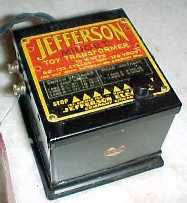
MIDGET
Toy Transformer
50 watts capacity
 Jefferson
Electric Mfg Co., Chicago, Ill. For use with 110V 60 Cycle. The line cord is
made of two separate wires with black cloth on the outside. These are twisted
together and exit the transformer case through a porcelain grommet that says
Jefferson. The other end has an old style plastic two-prong plug. The
transformer case is fastened to a square dish shaped bottom plate at four
raised points near the corners. Terminals 1 and 2 are at the left side.
Terminals 3 and R are at the right side. The nameplate is black and silver.
Jefferson
Electric Mfg Co., Chicago, Ill. For use with 110V 60 Cycle. The line cord is
made of two separate wires with black cloth on the outside. These are twisted
together and exit the transformer case through a porcelain grommet that says
Jefferson. The other end has an old style plastic two-prong plug. The
transformer case is fastened to a square dish shaped bottom plate at four
raised points near the corners. Terminals 1 and 2 are at the left side.
Terminals 3 and R are at the right side. The nameplate is black and silver.
The transformer case size is 2-3/4"H, 3-1/2"W and 3-1/2"D. Size including terminals, plate and slider knob is 3-1/16"H, 4-1/4"W and 4-1/4"D. Weight is 3.2 lbs.
|
Switch
Voltages |
Fixed
Voltages |
|
3 and R---1-1/2, 3, 4-1/2, 6, 7-1/2, 9 Volts |
1 and 2---6 Volts |
![]()
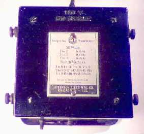
MIDGET
Toy transformer
75 watts capacity
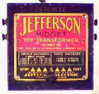 Delivers 18 secondary voltages ranging from 5-1/2 to
22-1/2 volts in 1 volt steps, with permanent voltages of 6 and 12 volts. Will
operate Ives trains--all "O" and Nos. 691, 692, 705, 710 and 711
standard gauge outfits, American Flyer--all "O" gauge and Nos. 342,
347, 350, 351 and 352 standard gauge outfits.
Delivers 18 secondary voltages ranging from 5-1/2 to
22-1/2 volts in 1 volt steps, with permanent voltages of 6 and 12 volts. Will
operate Ives trains--all "O" and Nos. 691, 692, 705, 710 and 711
standard gauge outfits, American Flyer--all "O" gauge and Nos. 342,
347, 350, 351 and 352 standard gauge outfits.
Jefferson Midget Toy Transformer. The 7 position linear slide switch is at the top front of the transformer and slides left and right. The detented positions are indicated by the gold colored triangles. Stamped in the top is a note 25 TO 40 CY. The left hand terminals are numbered 1 and 2. The right hand terminals are 3 and R. Rating is 75 watts for use with alternating current only. Made by Jefferson Electric Company, Chicago.
The line cord is made of two separate wires with black cloth on the outside. These are twisted together and exit the transformer case through a porcelain grommet that says Jefferson 100 1. The other end has an old style plastic two-prong plug. The transformer case is fastened to a square dish shaped bottom plate at four raised points near the corners. The transformer case size is 3-1/4"H, 4-1/16"W and 4-1/16"D. Size including terminals, plate and slider knob is 3-1/2"H, 4-5/8"W and 4-1/2"D. Weight is 5 lbs.
|
Switch
Voltages |
Fixed
Voltages |
|
1 and R---5-1/2 to 10-1/2 Volts |
1 and 2---6 Volts |
![]()
Jefferson
Transformer No. 535-171
Midget Toy Transformer (Improved)
75 Watts
 This was called an "improved type" and was
designed to be used at the higher line frequencies of 50/133 cycles. This meant
the volume of iron in the core could be decreased for the same performance. The
size of the box was reduced to 3"H, 3 1/2"W and 4"D. On the
label it says 100-120 volts 50-133 cycles. On the box it says for standard and
"O" gauge American Flyer, Ives "O" gauge and smaller sized
standard gauge, and Lionel"O" gauge and Nos. 347, 352,353 and 354
standard gauge.
This was called an "improved type" and was
designed to be used at the higher line frequencies of 50/133 cycles. This meant
the volume of iron in the core could be decreased for the same performance. The
size of the box was reduced to 3"H, 3 1/2"W and 4"D. On the
label it says 100-120 volts 50-133 cycles. On the box it says for standard and
"O" gauge American Flyer, Ives "O" gauge and smaller sized
standard gauge, and Lionel"O" gauge and Nos. 347, 352,353 and 354
standard gauge.
The 7 position linear slide switch is at the top front of the transformer and slides left and right. The detented positions are indicated by the gold colored triangles. The line cord is made of two separate wires with black cloth on the outside. These are twisted together and exit the transformer case through a porcelain grommet that says Jefferson 100 1. The other end has an old style plastic two-prong plug. The transformer case is fastened to a square dish shaped bottom plate at four raised points near the corners.
![]()
Jefferson
Universal Transformer No. 535-121
Midget Toy Transformer
75 Watts
For all standard and "O" gauge American Flyer, Ives "O" gauge and Nos. 691, 692, 701,and 711 standard gauge, and Lionel "O" gauge and Nos. 342, 347, 350, 351 and 352 standard gauge. Jefferson Electric Mfg. Co. 501-511 S. Green St., Chicago
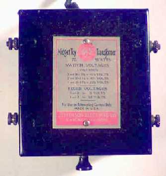
 This may be a later version of the Midget Toy
transformer. It has the same voltages and wattage. The model number is not
marked on the transformer but is on the box. The 7-position circular slide
switch is on the front instead of the top. The note stamped in the top says
"100 to 120V. 50 to 133 CY."
This may be a later version of the Midget Toy
transformer. It has the same voltages and wattage. The model number is not
marked on the transformer but is on the box. The 7-position circular slide
switch is on the front instead of the top. The note stamped in the top says
"100 to 120V. 50 to 133 CY."
The line cord is made of two separate wires with black cloth on the outside. These are twisted together and exit the transformer case through a porcelain grommet that says Jefferson 100 1. The other end has an old style plastic two-prong plug supplied with a screw base adapter for a lamp socket. The transformer case is fastened to a square dish shaped bottom plate at four raised points near the corners. The transformer case size is 2-3/4"H, 3-5/8"W and 4-1/16"D. Size including terminals, plate and slider knob is 3"H, 4-1/2"W and 4-3/4"D. Weight is 3.5 lbs.
![]()
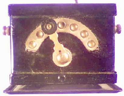
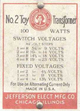
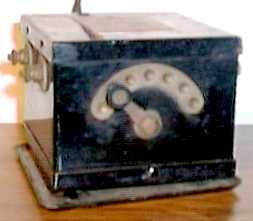
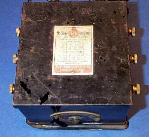
TYPE
No. 2--No. 535-131
100 watts capacity
 This model
delivers 25 secondary voltages from 5-1/2 to 23 volts in 3/4 volt steps.
Permanent voltages of 4-1/2, 9, and 13-1/2 volts. Will operate Ives trains--all
standard and "O" gauge outfits, Lionel trains--all standard and
"O" gauge outfits, Christmas tree lighting outfits, up to sixteen
14-volt lamps.
This model
delivers 25 secondary voltages from 5-1/2 to 23 volts in 3/4 volt steps.
Permanent voltages of 4-1/2, 9, and 13-1/2 volts. Will operate Ives trains--all
standard and "O" gauge outfits, Lionel trains--all standard and
"O" gauge outfits, Christmas tree lighting outfits, up to sixteen
14-volt lamps.
Jefferson No. 2 Toy Transformer 100 Watts. For 100 to 120V 50 to 133 CY. For Use On Alternating Current Only. The 7 position circular slider is mounted on the front of the transformer. The left hand terminals are numbered 1 and 2. The right hand terminals are 3, 4 and R. Made by Jefferson Electric Mfg. Co. Chicago, Illinois
|
Switch
Voltages |
Fixed
Voltages |
|
1 and R---5-1/2 to 9 Volts |
1 and 2---4-1/2 Volts |
![]()
TYPE
No. 3--No. 535-141
150 watts capacity
 Delivers 25 secondary voltages from 1.2 to 30 volts in
1.2-volt steps. Permanent voltages of 6, 12, 18 and 24 volts. Will operate all
types of electrical trains up to the largest and most expensive, and should be
recommended when extra cars and accessories are used with standard outfits.
Will also operate Christmas tree outfits up to thirty two 14 volt lamps.
Delivers 25 secondary voltages from 1.2 to 30 volts in
1.2-volt steps. Permanent voltages of 6, 12, 18 and 24 volts. Will operate all
types of electrical trains up to the largest and most expensive, and should be
recommended when extra cars and accessories are used with standard outfits.
Will also operate Christmas tree outfits up to thirty two 14 volt lamps.
For 100 to 120V 50 to 133 CY. For Use On Alternating Current Only. The 7 position circular slider switch is mounted on the front of the transformer. The left hand terminals are numbered 1, 2 and 3. The right hand terminals are 4, 5 and R. Size is 4"H, 5"W and 5-1/4"D.
|
Switch
Voltages |
Fixed
Voltages |
|
1 and R---1.2 to 6 Volts |
1 and 2---6 Volts |
![]()
Jefferson
Toy Transformer--No. 535-191
150 watts capacity
Primary 100/120 Volts--50/60 cycles. Secondary voltage has a continuously variable control as well as fixed voltages. Jefferson Electric Company, Bellwood, Illinois.
|
Switch
Voltages |
Fixed
Voltages |
|
1 and R---1 to 6 Volts |
1 and 2---6 Volts |
![]()
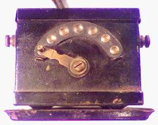
Jefferson
Stream Liner No. 535-271
75 watts capacity
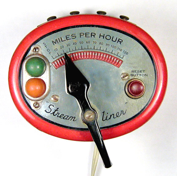
The pointer is mad of formed sheet metal and painted black. It can be rotated to make contact with multiple voltage taps in the semicircle for the different speeds. The green lamp lights when the transformer is plugged in. The red light may indicate that the reset button must be pushed.
|
|
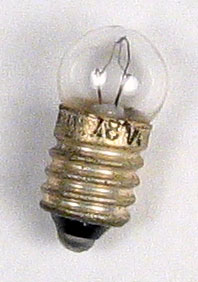
The lamp cover can be removed to replace the lamps. Writing on the lamp is not perfectly clear. It could be 18 volt or possibly 28 volt. The open circuit voltage at the lamp socket is about 15 volts and the lamp is not that bright when it is on. The base is threaded and is type E-10. The colored lamp lenses are plastic |

The left pair of taps provides a variable
voltage from 8 to 16 volts.
The first and third taps are variable from 16 to 25 volts
The center pair is 9 volts.
The right pair is 9 volts for the whistle.
The transformer is 3-3/4” high, 4-3/4” wiad and 4” deep. Rating ia 115 volts, 50/60 cycle alternating current only.
![]()
SIGNALING TRANSFORMER--No. 231-101
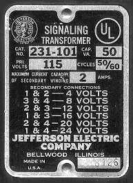 This is undoubtedly a later design and with the new
Jefferson address. Capacity 50 Volt-Amps, Primary volts 115, cycles 50/60,
Maximum current capacity of secondary winding 2 amps. Serial number stamped in
the plate is 218126.
This is undoubtedly a later design and with the new
Jefferson address. Capacity 50 Volt-Amps, Primary volts 115, cycles 50/60,
Maximum current capacity of secondary winding 2 amps. Serial number stamped in
the plate is 218126.
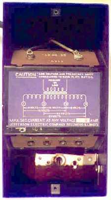 The top cover can be removed to select the connections
for the desired voltages. The two primary connections are in the top section.
The four secondary connections are in the bottom section. A 35 ohm 25 watt
control is mounted in the top cover (not shown). The control shaft is 2"
long and has a screwdriver slot at the end. A 3-prong Amphenol socket is
mounted on the right bottom side. I found two rectifier diodes mounted on a
circuit board inside plus a 500 mfd 50V-filter capacitor (at the bottom). The
control appears to have been added by someone at a later date. I don't know if
the rectifiers, capacitor and socket are standard or were also added by someone
later. The diodes and capacitor provide a filtered DC output for the secondary
transformer voltages. The control provides a continuously variable voltage for
the transformer taps selected.
The top cover can be removed to select the connections
for the desired voltages. The two primary connections are in the top section.
The four secondary connections are in the bottom section. A 35 ohm 25 watt
control is mounted in the top cover (not shown). The control shaft is 2"
long and has a screwdriver slot at the end. A 3-prong Amphenol socket is
mounted on the right bottom side. I found two rectifier diodes mounted on a
circuit board inside plus a 500 mfd 50V-filter capacitor (at the bottom). The
control appears to have been added by someone at a later date. I don't know if
the rectifiers, capacitor and socket are standard or were also added by someone
later. The diodes and capacitor provide a filtered DC output for the secondary
transformer voltages. The control provides a continuously variable voltage for
the transformer taps selected.
The transformer has brackets at each end at the bottom. There are holes and slots where it can be permanently mounted to a board. Height (including brackets) is 3-7/8", width is 4-3/16 and depth is (including brackets) 8-5/8".
![]()
Jefferson Electric Luminous Tube Transformer
Catalog No. 721-101-100 Outdoor Non-Weatherproof type. Pri. 120V 60HZ. 160VA. Sec. 5000V 30 mA. Sec. Start Grounded. A9001 may indicate a date of manufacture of 1990. MagnaTek Jefferson Electric. The transformer case size is 3-5/8"H, 3-1/8"W and 4-5/8"D. Depth including terminals is 7-3/8". Weight is 6.7 lbs.
![]()
 Catalog No. 721-111 Outdoor Non-Weatherproof type.
Pri. 120V 60HZ. 450 VA. Sec. 15,000V 30 mA. Sec. Midpoint Grounded. J7405 may
indicate a date of manufacture of 1974. Jefferson Electric, Division of Litton
Industries, Bellwood, Ill.
Catalog No. 721-111 Outdoor Non-Weatherproof type.
Pri. 120V 60HZ. 450 VA. Sec. 15,000V 30 mA. Sec. Midpoint Grounded. J7405 may
indicate a date of manufacture of 1974. Jefferson Electric, Division of Litton
Industries, Bellwood, Ill.
![]()
Jefferson Electric Luminous Tube Transformer
Catalog No. 721-131 Outdoor Non-Weatherproof type. Pri. 120V 60HZ. 180 VA. Sec. 6000V 30 mA. Sec. Midpoint Grounded. A/C power cord has been added. Measures about 8" x 3" x 4". This transformer was removed from a neon sign assembly.
![]()
Jefferson Electric Luminous Tube Transformer
Catalog No. 725-151-700 Outdoor Non-Weatherproof type. Pri. 120V 60 Hz 225 VA. Sec. 7500V 30 mA. Sec. Midpoint Grounded. The A8709 probably indicates a date of manufacture of 1987. Size 3" X 3-1/2" X 9". Weight 12 lbs.
![]()
Magnetek Jefferson Luminous Tube Transformer
Catalog No. 725-141-041 Outdoor Non-Weatherproof type. Pri. 120V 60Hz 270 VA. Sec. 9000V 30 mA Sec. Midpoint Grounded. The m 95 05 probably indicates a date of manufacture of 1995.
![]()
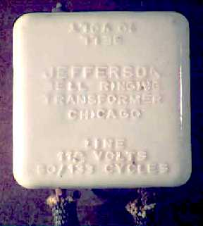
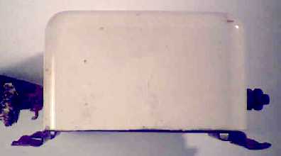 This
early bell-ringing transformer is a single block of white glazed porcelain
1/4" thick that's open in the back. The transformer is inside and is
covered with a tar potting material. A metal mounting bracket is attached
through holes in the porcelain sides. The words "Pat'd Dec 1, 1925 U.S.A.
3-31" are stamped in the bracket. This is probably the date of March 1931.
7" insulated primary wires are brought out through two other holes. Two
secondary binding post terminals are at the other end. Cast into the porcelain
in raised letters are "Line 110 volts 50/133 cycles" at the primary
end and "Bell 10 volts" at the other end. In the middle is
"Jefferson Bell Ringing Transformer, Chicago. Size of the porcelain
container is 3-1/8 X 3-1/8" X 1-7/8"
This
early bell-ringing transformer is a single block of white glazed porcelain
1/4" thick that's open in the back. The transformer is inside and is
covered with a tar potting material. A metal mounting bracket is attached
through holes in the porcelain sides. The words "Pat'd Dec 1, 1925 U.S.A.
3-31" are stamped in the bracket. This is probably the date of March 1931.
7" insulated primary wires are brought out through two other holes. Two
secondary binding post terminals are at the other end. Cast into the porcelain
in raised letters are "Line 110 volts 50/133 cycles" at the primary
end and "Bell 10 volts" at the other end. In the middle is
"Jefferson Bell Ringing Transformer, Chicago. Size of the porcelain
container is 3-1/8 X 3-1/8" X 1-7/8"
![]()
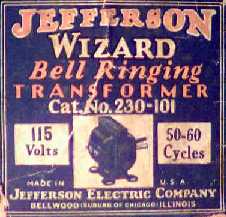 Catalog
number 230-101. Made by Jefferson Electric Company, Bellwood, Illinois. Here is
a later bell-ringing transformer. It has two 5-1/2" primary wires on one
side and two secondary screw terminals on the other side.
Catalog
number 230-101. Made by Jefferson Electric Company, Bellwood, Illinois. Here is
a later bell-ringing transformer. It has two 5-1/2" primary wires on one
side and two secondary screw terminals on the other side.
Size is 2-1/2" high, 2-1/4" wide and 2" deep. Weight is 3/4 lbs. It is painted black. Capacity is 5 watts. It has a UL approval seal.
![]()
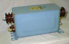
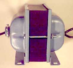 Catalog No. 637-271. Made by Jefferson Electric. This
industrial control transformer is rated at 50/60 Hz. Primary 120V, Secondary
24V at 150 VA (6-1/4 amps). The number on the label is W8205, which may be the
date of May 1982. Case color is blue-gray and the core is black. Primary wires
are 7" long made by Belden. The transformer is UL approved. Size
4-1/8"H, 3-1/4"W and 4-3/8"D (including threaded wire exit).
Weight is 6 lbs.
Catalog No. 637-271. Made by Jefferson Electric. This
industrial control transformer is rated at 50/60 Hz. Primary 120V, Secondary
24V at 150 VA (6-1/4 amps). The number on the label is W8205, which may be the
date of May 1982. Case color is blue-gray and the core is black. Primary wires
are 7" long made by Belden. The transformer is UL approved. Size
4-1/8"H, 3-1/4"W and 4-3/8"D (including threaded wire exit).
Weight is 6 lbs.
![]()
Catalog No. 216-1421. Made by Jefferson Electric, Division of Litton Industries, Bellwood, IL. This dry type transformer is in a gray steel case. The transformer is potted in a sand/epoxy mixture. It is rated at 50/60 Hz single phase. High volt is 240/480V and low volt is 24/48V at 250kVA (24V at 10.4 amps and 48V at 5.2 amps). (The number on the label is J8201, which may be the date of January 1982. Size is approximately 3-3/4"H, 4"W and 9"D.
![]()
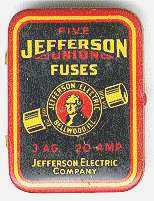 Here's a
box of five Jefferson Union Fuses 3AG type at 20 amps.
Here's a
box of five Jefferson Union Fuses 3AG type at 20 amps.
The writing on the back says:
" Fuses are necessary for the protection of an electrical system, including that of your car. A fuse 'blows' when the electrical system is overloaded to the point of danger to apparatus and wiring. Union fuses are constructed accurately to burn out at this danger point. When a fuse 'blows' and the replacement fuse also burns out immediately, look for trouble in the electrical system. Do not attempt to use pieces of wire or larger fuses"
 The box size is 3/8" thick, 1-3/8" wide and
1-13/16" long. Weight with the fuses is 0.6 ounces. The address is
Jefferson Electric Company, Bellwood, ILL.
The box size is 3/8" thick, 1-3/8" wide and
1-13/16" long. Weight with the fuses is 0.6 ounces. The address is
Jefferson Electric Company, Bellwood, ILL.
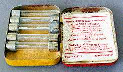
Inside the box it says:
"Other Jefferson products
TRANSFORMERS:
Radio Replacement
Luminous tube sign
Oil Burner Ignition Control
Door Bell and Signal Toy
Auto and Double Wound
--------------------
Outlet and Switch Boxes
Cut-out Bases and Clips
Metal Clad Mercury Switches"
Many other Jefferson fuse boxes have been found with several different art layouts and addresses.
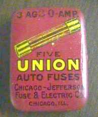 This box contains five 3AG 3.0 amp fuses. The name on
the box is Chicago-Jefferson Fuse & Transformer Company, Chicago, Ill. This
is an earlier address than the one above
This box contains five 3AG 3.0 amp fuses. The name on
the box is Chicago-Jefferson Fuse & Transformer Company, Chicago, Ill. This
is an earlier address than the one above
![]()
Jefferson Renewal Links
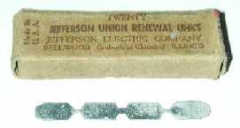 Catalog number 381-030. Jefferson Union Renewal Links.
These fusible links can be used to replace a burned out link in a fuse holder.
They come 20 to a box. They are rated at 30 amps and 250 Volts. The box size is
1/2" high, 2-5/8" wide and 3/4" deep. The back of the box has an
underwriter's inspection label.
Catalog number 381-030. Jefferson Union Renewal Links.
These fusible links can be used to replace a burned out link in a fuse holder.
They come 20 to a box. They are rated at 30 amps and 250 Volts. The box size is
1/2" high, 2-5/8" wide and 3/4" deep. The back of the box has an
underwriter's inspection label.
Each link measures 0.011" thick, 2-1/4" wide and 1/4" deep. The narrow portion at either end is .048". The center narrow part is 0.10". Imprinted in the metal is "UNION 250 V and 30 is at either end. The tabs must be bent at right angles about 1/4" from each end to stay in place. Patent dates on a competitor's link found in the box are 8-15-16 and 2-27-17. This is possibly 1916 and 1917.
![]()
Jefferson Gem Plug Fuses
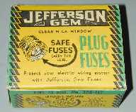 Jefferson also made standard home type fuses. This box
contains five 15 amp fuses. The part number is 388-115. The box is 1-1/4"
high, 2-3/4" wide and 1-1/4" deep. Jefferson Electric Company,
Bellwood, Illinois. The instructions on the box say:
Jefferson also made standard home type fuses. This box
contains five 15 amp fuses. The part number is 388-115. The box is 1-1/4"
high, 2-3/4" wide and 1-1/4" deep. Jefferson Electric Company,
Bellwood, Illinois. The instructions on the box say:
"Be Sure to Use Fuse of the Proper Capacity"
"For home lighting branch circuits use Jefferson 6, 10, 12, and 15 ampere fuses, depending upon the total ratings of lamps and appliances on each circuit. Use sizes over 15 amperes for main line circuits only. All Jefferson plug fuses are listed by and bear Underwriters Laboratories label for use on 110 to 125 volt circuits."
"How to Install"
"Open the main switch, go to the fuse panel and reflace all burned out fuses with Jefferson clear window fuses which permit you to see at a glance whether or not the fuse element is intact. Then close the main switch and the circuit again be in service. If fuses continue to blow, call your electrical dealer or lighting company. . and had the old mica window."
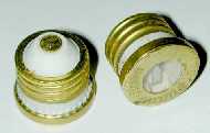 Here is a 25 and 30 amp fuse in the same style. They
have a clear mica window. The top, threads and base are made of brass. On the
top it say Jefferson Electric and the current rating. The current rating is also
imprinted on the base. The main body is porcelain. The top is 1-1/8" in
diameter and the threads are 1" in diameter. The height is 1-1/8".
Weight is 25.5 grams or almost 1 ounce.
Here is a 25 and 30 amp fuse in the same style. They
have a clear mica window. The top, threads and base are made of brass. On the
top it say Jefferson Electric and the current rating. The current rating is also
imprinted on the base. The main body is porcelain. The top is 1-1/8" in
diameter and the threads are 1" in diameter. The height is 1-1/8".
Weight is 25.5 grams or almost 1 ounce.
![]()
Industrial Fuses
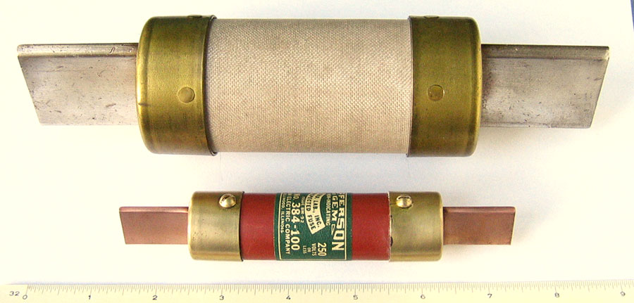
Jefferson also made very large fuses. The top is one is 8-3/4" long and 2-1/16" in diameter. It weighs 927 grams or just a little over 2 pounds. The exposed knife-blade contacts are 1-5/8" X 1-7/8" and 1/4" thick. They are solid copper that is silver-plated. The brass cups at each end are riveted in place. The words 400 A 500 V and J. E. CO are stamped on the side of one of the cups.
Information on the cardboard box that it came in says:
|
Stock No P 17-F-17472-4000 |
S.C. Order No. N 151-219S-91311 |
Arc-quenching fuse tubes are used to suppress
and/or quench electrical arcing when the fuse material inside blows. Arcing can
occur when fuse link melting is induced by a fault during operation of an
electrical system. To restore normal operation of the system, it is desirable
to suppress the arc and clear the fault. Fuse tubes may serve this purpose, and
are preferably capable of suppressing and removing arcing conditions. Some
fuses have replaceable elements and the tubes must be able to be reused several
times.
Fuse tubes, and especially the inner surfaces of fuse tubes, are typically
formulated from horn fiber, also referred to as bone fiber. Horn fiber is a
naturally-occurring substance and is composed largely of keratinous material,
which is a tough, fibrous protein. Upon exposure to an electrical arc, horn
fiber can decompose, typically by vaporization. This decomposition generally
results in the rapid generation and evolution of gases which interrupt and quench
the electrical arc. Horn fiber also possesses desirable mechanical strength and
is generally capable of withstanding the high temperature and pressure conditions that can be created by electrical
arcs. The manufacture of horn fiber and products which contain horn fiber, such
as fuse tubes, is difficult and time-consuming. This tends to increase the cost
of horn fiber and horn fiber products.
The use of horn fiber is mentioned in the 1928 catalog number thirty three of
the Chicago-Jefferson Fuse & Electric Co. However, horn fiber may be
obsolete today being replaced by cheaper and more effective materials.
The lower fuse is for 250 volt 100 amp service. The blade contacts are solid copper and are not plated..
![]()
These directions came with a Jefferson Toy Transformer
Directions for Operating
Jefferson Toy Transformers
With Special Instructions for
Trouble Finding
Caution
Ninety percent of all transformer trouble is caused by permitting the train to lie across the rails and cause a short circuit when it jumps or is knocked off the track.
Naturally, if there is a short circuit, the load on the transformer is much greater than it is designed to carry and it may burn out if permitted to remain in that position.
Each transformer has its rated capacity, but will stand a 25% overload. They should not be expected to take care of a heavier load.
If the transformer is operated on an overload or short-circuit, it will heat up. We recommend placing your hand on the transformer after 15 or 20 minutes' use. If it becomes very warm, it is an indication of too heavy a load or a short circuit and should be disconnected at once.
This transformer is intended for intermittent service and should be used only for short periods at a time. Be sure to turn off the current when train outfit is not in use.
Remember, burn-outs are only liable from short circuits, overloads, and continuous service.
This transformer is purely a toy device and is not designed for continuous or commercial service. It will operate from alternating current only, of the voltage and frequency specified on the transformer. If you are not certain of the current, call your electric light company before attaching transformer to the house circuit. This precaution must be taken, or you may ruin the transformer.
A 110-volt, 60-cycle transformer will operate successfully on voltages ranging from 100 to 120 volts, and 50 to 133 cycles. A 25-cycle transformer will operate on frequencies of from 25 to 40 cycles.
Make all connections from transformer to tracks or accessories before attaching to the house circuit, and be sure to have current shut off when you screw in the plug from the transformer. Two lead wires are furnished with each transformer. Scrape the insulation off the ends of the wires, before attaching to transformer and track.
While Jefferson Transformers will easily stand a 25% overload without harm, we recommend shutting off the current immediately when you stop the train, or when the train jumps the track.
Different sizes of trains require different secondary voltages. For instance, you have a Midget transformer and desire 14-1/2 volts. Connections are made from the track to posts marked R and 2 and advance the switch lever to the fifth contact. If less voltage is desired move switch lever to left; for more power, move to right. If 6 volts are wanted for lighting small lamps, connect one wire, to post No. 1 and the other to No. 2, attaching the other ends to the lamp binding posts.
Other voltages may be obtained by combining the various posts. The nameplate on the cover shows how to obtain the various voltages. If your train instructions do not specify the voltage to use, attach the wires to posts R and 1 first. If that does not give enough power to pull the train, attach the wires to posts R and 2, etc., until the necessary voltage is available. Any of the low voltages may be used singly or simultaneously. Also any number of leads of the same voltage may be used at the same time, provided the section in use is not overloaded.
Toys and other electrical apparatus that require a given battery voltage to operate require 3 to 7 volts higher voltage alternating current to do the same work. For instance, a toy train requiring 8 volts direct current will take about 11 volts alternating to do the same work, and it may be run on a trifle higher voltage without any harmful effects.
Special Instructions
During past years, transformers have been returned which owners claimed are defective. In a large majority of cases we found, after investigating, that the transformer was all right and that the fault was with some other part of the train system. We give you, therefore, a few hints as to what to look for in case the train does not work when connections are made.
Directions for Operating Electric Trains
When the attachment plug of the Jefferson Transformer is connected to the alternating current lighting circuit, the power is ready. Always start the train with a minimum amount of current and add more voltage by moving the regulating switch from left to right. Before placing locomotive on track see that the current is turned off. If the locomotive has a reversing controller, see that it is pushed forward or backward as far as possible.
If directions have been carefully followed, the locomotive should start when the power is switched on. Yet it sometimes happens that the locomotive may have been slightly injured by careless handling or from rough treatment in shipping. Usually the trouble is so slight that by following our suggestions you will be able to correct it.
To Test Locomotive
Disconnect the two wires running from the track terminals leaving wires attached to Transformer. Turn locomotive upside down and hold one wire on motor frame; with the other wire touch shoe, which collects the current from the third rail. If locomotive has a reversing controller, be sure it is set backward or forward. If locomotive is 0. K., wheels will revolve. The voltage, which will cause wheels to turn idly, is not sufficient to operate it when on the track, so after you replace locomotive on track, give it more power than you did while testing it. If it still refuses to move, it may be that the track is short-circuited or open circuited. Short-circuit means that the current of electricity is taking a shorter way back to the Transformer through some metallic connection between the middle rail and outside rail or between connecting wires. Open circuited means that all sections of the track are not properly connected.
Finding Short Circuit on Track
Be sure that all sections on track fit snugly together and that nothing lies across or stands on the track, not even the locomotive. Make sure that no metal is in contact with outside and center rail. Then with two wires running from Transformer hold one wire to outside rail and brush the end of the other wire across the center rail. If the track is perfectly insulated, no sparks will occur when you brush the wire across it; but if it is short-circuited, a spark will occur where the wire touches.
Next locate the short-circuited section. Disconnect one section at a time and apply the wires to the remaining sections as above. As soon as the defective section is removed, the sparking will stop. Or disconnect all sections and test each separately. The one that sparks is defective.
Clean the track with a cloth dampened in kerosene and then wipe perfectly dry. This is important
How
to Get Power from Jefferson Transformers
to Toy Electric Lamp Post, Station and
Semaphores
Always use set voltages only for lighting lamp posts, semaphores, etc., running separate wiring for this purpose. The regulator should be used only for operating the train at various speeds.
When electric railway accessories are to be used, we suggest that you tack the track down on a board or table. This should be a little larger than the track to be used. Fasten down the accessories with small screws. When connecting accessories to transformer make sure the lamp voltage corresponds with the voltage being taken from Transformer.
Do not permit the lights to burn continuously. The transformer is not intended for continuous service.
Operating
Christmas Tree Lights with
Transformers
Christmas tree lights wired in multiple can be operated through Jefferson Transformers. The principal advantage of multiple wired lights is the fact that should one light burn out the others are not affected. With the series system one burnt out lamp puts out all the others on the same circuit, making it difficult to locate the defective one.
The No. 2 Transformer will operate as many as sixteen14-volt lamps. Eight of the lights should be connected between binding posts "1" and "4" and eight between "2" and "R."
The No. 3 type will operate up to thirty-two 14-volt lamps by connecting half of the number of lamps between binding posts "1" and "3," and half between "2" and "R."
Extra
Wires Enclosed with
Transformers
Two leads of wire are enclosed with each Jefferson transformer to be used in connecting the toys to the binding posts.
Our Guarantee
Jefferson Toy Transformers are guaranteed to be mechanically perfect when leaving our factory.
Any transformer, which proves defective through poor material or workmanship, will be repaired or replaced free of charge.
If the transformer is abused either by overloading or a short circuit, repairs or replacement will be made at factory cost. Transportation charges must be prepaid on all returns.
Guarantee void if transformer is opened, tampered with or not used according to instructions.
![]()
|
About This Site |
||
|
|
More text and pictures about Jefferson will be added as my research continues. Any comments, corrections, or additions are welcome. |
|
|
|
|
Created
by Roger Russell |