McIntosh XR290 Speaker System
A History
These pages are copyrighted.
No portion of this site may be reproduced in whole or in part
without written permission of the author.
![]()
 Carl and I started work on the XR290 in 1990. The
objective was to create a version of the XRT20 and XRT22 that was contained all
in one cabinet. This avoided two separate enclosures and a stand that took up
45" of floor space. The new design was much narrower. I decided that a
cabinet this tall could enclose four woofers instead of two and offer higher
power handling like the earlier ML-4's. I already had a patent on the use of
the tweeter column from earlier designs.
Carl and I started work on the XR290 in 1990. The
objective was to create a version of the XRT20 and XRT22 that was contained all
in one cabinet. This avoided two separate enclosures and a stand that took up
45" of floor space. The new design was much narrower. I decided that a
cabinet this tall could enclose four woofers instead of two and offer higher
power handling like the earlier ML-4's. I already had a patent on the use of
the tweeter column from earlier designs.
The drivers we used in various earlier systems were already proven for their good performance and reliability. We had been making the woofers and midranges at McIntosh for several years. As a further improvement, we added Carl's new LD/HP magnet structure to the woofers. They had much lower distortion in the upper bass than earlier woofers by a factor of 10. Voice was incredibly clear. They also had polyether surrounds that were very light, linear and resonance free.
Our first prototype was seven feet tall and 25" wide. It contained a column of twenty-four 1" soft dome tweeters and four 12" woofers. An 8" mid-range was located between the bottom and top two woofers. We soon found that sound bouncing off the floor from the mid-range interfered with the direct radiation. A second mid was added in the hope of canceling radiation to the floor, but this arrangement had a very restricted listening area. Finally, it became obvious to add a column of twelve 5" mid-ranges which avoided the floor bounce problem altogether. These excellent 5" midranges were previously used in the XR1051, XR1052 and XR250. We ended up with a triple column system, which was an expansion of the original tweeter column concept.
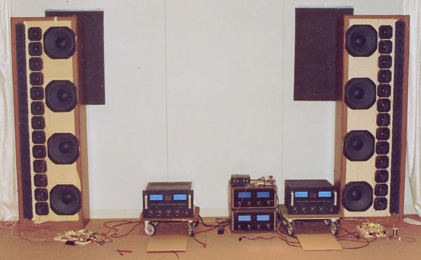 These are early XR290 prototypes in the picture, set
up in the listening room. Pardon the wide angle lens keystone distortion. All
the drivers were on the same flat front board. The crossovers were on the floor
where they could be easily modified and power tested. Two MC2600’s were on
dollies so they could be easily moved around. Each MC2600 was strapped for 1200
watt mono operation. Carl had covered the cabinets with vinyl wood grain sheets
from K-Mart for a better appearance. These became known as the K-Mart version.
These are early XR290 prototypes in the picture, set
up in the listening room. Pardon the wide angle lens keystone distortion. All
the drivers were on the same flat front board. The crossovers were on the floor
where they could be easily modified and power tested. Two MC2600’s were on
dollies so they could be easily moved around. Each MC2600 was strapped for 1200
watt mono operation. Carl had covered the cabinets with vinyl wood grain sheets
from K-Mart for a better appearance. These became known as the K-Mart version.
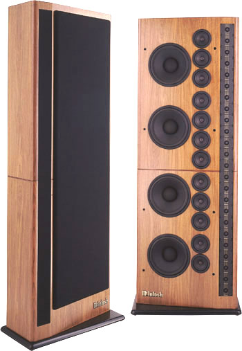
 Completion of the design was delayed until 1991
because Carl and I were assigned to develop a four-channel prototype speaker
system in the Infiniti Q45. The final XR290 prototype was not completed until
the fall of 1991. I decided to make the front panel for the woofers and mids
angle in very slightly. The tweeters faced directly forward. This did not
affect performance in any way but gave the XR290 a distinct and perhaps more
friendly styling. A separate tweeter grille was flush mounted against the
tweeters to avoid acoustic problems. The systems were made in left and right
hand versions and were placed in the room so that the tweeters were located at
the outside. This provided accurate stereo imaging between the systems and the
best arrival times for the individual columns in each system.
Completion of the design was delayed until 1991
because Carl and I were assigned to develop a four-channel prototype speaker
system in the Infiniti Q45. The final XR290 prototype was not completed until
the fall of 1991. I decided to make the front panel for the woofers and mids
angle in very slightly. The tweeters faced directly forward. This did not
affect performance in any way but gave the XR290 a distinct and perhaps more
friendly styling. A separate tweeter grille was flush mounted against the
tweeters to avoid acoustic problems. The systems were made in left and right
hand versions and were placed in the room so that the tweeters were located at
the outside. This provided accurate stereo imaging between the systems and the
best arrival times for the individual columns in each system.
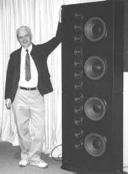
To get a rough idea of what the prototype weighed, we put it on my old bathroom scale and it went around for the second time totaling 320 lb. I hope this never happens to me! The cabinet was divided into an upper and lower section for easier handling and shipping. A dealer could assemble it in a customer's home. Two 1/2" threaded steel rods, washers and nuts held the sections together.
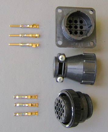 Internal electrical connectors joined the top and
bottom groups of drivers. A total of eight wires were needed between the
sections that went to the woofers, mids and tweeters. An arrangement of gold
plated pins and sockets was used. The wires were crimped and soldered to the
connecting pins and sockets. These were inserted into the holders and snapped
in place. The gold plating assured a more reliable connection and avoided
corrosion. See my section about Speaker
and Amplifier Connectors and my Gold Reference
page. A strain relief, shown in the center of the picture, could be screwed on
to the back of the plug and socket assembly. The pin assembly was mounted on a
steel bracket that was attached to one of the system sections. The connecting
parts were made by AMP Incorporated, Harrisburg, PA.
Internal electrical connectors joined the top and
bottom groups of drivers. A total of eight wires were needed between the
sections that went to the woofers, mids and tweeters. An arrangement of gold
plated pins and sockets was used. The wires were crimped and soldered to the
connecting pins and sockets. These were inserted into the holders and snapped
in place. The gold plating assured a more reliable connection and avoided
corrosion. See my section about Speaker
and Amplifier Connectors and my Gold Reference
page. A strain relief, shown in the center of the picture, could be screwed on
to the back of the plug and socket assembly. The pin assembly was mounted on a
steel bracket that was attached to one of the system sections. The connecting
parts were made by AMP Incorporated, Harrisburg, PA.
This was the first McIntosh system with the option of bi-amp or tri-amp operation. It was a sales feature rather than a performance advantage. Three gold plated dual connectors were at the rear of the system for the woofers, mids and tweeters. Two removable gold plated straps connected the three sets together. The crossover network for each column remained connected between the drivers and the input terminals. The unique passive network used in the XR290 was custom tailored for the drivers and had mid-band elements that further smoothed response. Each crossover still had to be used even if the system was bi-amped or tri-amped .Electronic crossovers were not needed or recommended.
![]()
Advantages of the McIntosh XR290
One of the first lessons in speaker design is learning that bigger is not always better. Instead, it depends on how well the system is designed. Although the XR290 was big and had a total of 40 drivers, it was divided into three columns. Each column could be considered as one long driver, making it only a three-way system.
Even though the columns didn’t stretch out to infinity, they still behaved like a line source when they ran from floor to ceiling in the listening room. It meant you get the same sound whether you were standing or sitting or at any other height.
Radiation from a point source driver, which is used in most system designs, is invariably affected at the listening position because of reflections, particularly from the floor but also from the ceiling. The reflections combine with the direct sound from the speakers and cause uneven response. However, radiation from the long column is very directional vertically. Sound radiated to the floor and ceiling from the XR290 was almost non-existent and dramatically and eliminated reflections. The power handling was exceptional due to the large number of drivers in each column. Each driver received only a fraction of the system input power. Consequently, distortion was very low, even at very loud listening levels. For example: one XR290 tweeter had only 0.3% distortion at 10 watts input. A system input of 240 watts at high frequencies delivered to 24 tweeters still had only 0.3% distortion.
Courtesy of Charles Rodrigues
The XR290 had accuracy in imaging, depth and spaciousness that was outstanding. It was particularly good in revealing how recordings were mixed. The sound field reproduced by this system reminded me of a similar listening experience when playing speakers in our full sized reflection free anechoic chamber.
Another misconception with encountering big speakers is that they're too loud. The truth is that the XR290's will play as soft or as loud as you want them to play. Reserve power in the amplifier and reserve, low distortion power handling of the speaker system were a great advantage for playing music. The softest passages may have only required less than 1 watt for a normal listening level. But, when the loud passages came along, peak power demands could easily be 1000 times higher. This was no problem for the XR290.
The woofer, mid and tweeter sections each had a bi-stable solid state current sensor to protect them. If any part of the XR290 was overdriven, these would act to protect the speakers. The sensors could be easily reset by turning the volume down for 10 seconds.
The XR290 output was rated at 87 dB at one watt at one meter referred to 8 ohms. Was this high or low? A few years ago we tested a large number of speakers for sensitivity in our large anechoic chamber. Oddly enough, most of the speakers measured below their claimed sensitivity. None were above! Only one B&W system was as advertised. Perhaps there was a little science fiction added by the advertising departments. A new way to get higher numbers these days is to reference the sensitivity to 2.83 Volts instead of 1 watt. This way a 4-ohm speaker can claim a 3 dB higher sensitivity, ignoring the fact that the power into 4 ohms for 2.83 Volts is 2 watts and not one! The XR290 is 87 dB at one watt.
So how did the XR290 really compare? You must remember that the XR290 radiated a cylindrical wave front and each doubling of distance reduced the sound level by only 3dB, whereas the sound level for system having point source drivers, such as for a single tweeter, has a spherical wave front and decreases in sound level by 6dB. It means that, the sound level of the XR290 can be higher than a common system having the same sensitivity.
|
|
XR290 |
Typical
System |
|
3 feet |
87 dB |
87 dB |
|
6 feet |
84 dB |
81 dB |
|
12 feet |
81 dB |
75 dB |
Owner Medallions
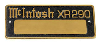
Gold plated owner medallions were available by sending in a registration form. The form required the owner’s name as they would like it to appear on the medallions. You also had to include the serial numbers of the systems located at the loudspeaker connecting panel on the lower back of each system. Within 90 days you will receive the medallions with owner’s name and serial numbers engraved on them. They measure 3-1/2" wide and 1-1/2" high. They can be attached to each XR290 system on the front panel behind the grille, just below the top woofer. Mounting holes are already provided.
![]()
I am pleased after all these years that my column solution to power handling and my patent has continued to be successfully marketed by McIntosh. It has been almost 30 years since I had constructed the first prototype. The advantages of the column in home systems are too good to ignore. See my page about my experience with columns.
![]()
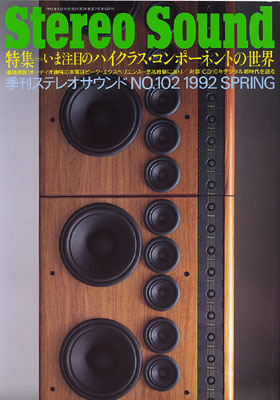
The XR290 was featured on the cover of the Japanese magazine Stereo Sound in the spring of 1992. It also received a prestigious Japanese award after I had left McIntosh. The XR290 was sold for almost 10 years before it was discontinued in 2001.
![]()
|
|
|
After the design was completed, the work was far from finished. I prepared a bill of materials for the entire system. The bill of materials was divided into subassemblies. If new parts were used, I wrote out a new part number request describing the part and the vendor. For the crossover subassembly, I made a pictorial layout of the board, including the location of the holes, where solder lugs were to be riveted. There was also a wire list specifying the wire size, color, lengths and connectors. Because of the number of drivers and the need for an interconnecting plug and socket between the top and bottom sections, the list was unusually complex. However, production had a custom wire coloring machine that made purchasing and inventory much easier to handle. White wire was purchased and then colored as needed.
The woofers and mid-ranges were made by McIntosh and a separate bill of materials was required. The packing bill of materials was provided by engineering. I wrote the production test specifications for the crossover boards, drivers and finished systems. I also provided a sample wiring board for production. Production occasionally sent boards or drivers to the lab for testing if they were outside of the test of limits.
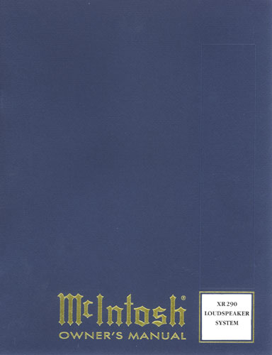
In addition to all of this, I was involved in writing the owner and service manuals. The owner’s manual contained a description of the design features and the system components. There was a brief description of the circuitry as well as the specifications. The cover for the owner’s manual was a new design. The cover was universal with a square hole cut at the bottom right corner. The system name showed through from the next page. The service information contained schematic diagrams and pictorials of the crossover board. Specifications were also included.
There were often several printings of the owner’s manual. The cover appearance was sometimes changed and minor changes sometimes made to the text. There were sometimes changes made to the service information as well. If there was a change in the circuitry or parts, new service information might be issued with the corresponding serial numbers indicated on the cover. If the changes were minor, a service bulletin was issued instead. Each issue of the manuals and bulletins could be identified at the back or on the bottom. For example, the back cover of this owner’s manual had the numbers 039-886.
![]()
XR290 Specifications
Response: 20Hz to 20,000Hz
Power rating: up to 1200 watts on program peaks
Output sensitivity: 87dB/watt/meter re: 8 ohms
Impedance: 8 ohms
Woofers: four 12" McIntosh LD/HP
Mid-range: twelve 5" McIntosh
Tweeters: twenty four 1" custom soft domes
Crossover frequencies: 400Hz and 1300Hz
Overload protection: solid state current sensors for woofers, mid-ranges and
tweeters
Finish: walnut, oak or black ash
Dimensions: 83-3/4" high, 28-3/4" wide and 12-1/2" deep
Weight: 335 lb.
Sold from 1992 to 2001
Last retail price $27,500
The XR290 was available by special order
only.
It was later available in black ash.
Prices were as follows:
Oak or walnut $24,950
Rosewood lacquer finish $34,950
Black polyester gloss $44,950
Rosewood polyester gloss finish $54,950
![]()
|
About This Site |
||
|
|
More text and pictures about McIntosh will be added as my research continues. Any comments, corrections, or additions are welcome. |
|
|
|
Created
by Roger Russell |
|