McIntosh XRT20 Speaker System
A History
Patent
number 4,267,405
"Stereo Speaker System For Creating Stereo Images"
Patent
number Des. 261,883
"Speaker Assembly"
Copyright 1996-2005 by Roger Russell
All rights reserved
No portion of this site may be reproduced in whole or in part
without written permission of the author.
![]()
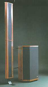 For a conservative company like McIntosh, my concept
of the XRT20 speaker system was very radical. The size, shape and two piece
construction was very different from the traditional designs of earlier
McIntosh systems. However, the XRT20 upheld the McIntosh tradition of
excellence and performance. It fulfilled several fundamental requirements.
Based on my past experience, there was a definite need for a speaker system
that handled more power at mid and high frequencies. The McIntosh electronics
section was making higher power amplifiers and we didn’t have a speaker that
would handle it. In addition, there were many amplifiers, including older
McIntosh units that didn’t have Power Guard to prevent "clipping" at
higher power. For systems having only a single mid-range or tweeter, the
distortion products in a badly clipping amplifier could have enough energy to burn
out the mid-range or tweeter.
For a conservative company like McIntosh, my concept
of the XRT20 speaker system was very radical. The size, shape and two piece
construction was very different from the traditional designs of earlier
McIntosh systems. However, the XRT20 upheld the McIntosh tradition of
excellence and performance. It fulfilled several fundamental requirements.
Based on my past experience, there was a definite need for a speaker system
that handled more power at mid and high frequencies. The McIntosh electronics
section was making higher power amplifiers and we didn’t have a speaker that
would handle it. In addition, there were many amplifiers, including older
McIntosh units that didn’t have Power Guard to prevent "clipping" at
higher power. For systems having only a single mid-range or tweeter, the
distortion products in a badly clipping amplifier could have enough energy to burn
out the mid-range or tweeter.
Multiple tweeters could be used to increase power handling, but using several tweeters that covered the same frequency range was normally a bad thing to do. A short column of closely spaced tweeters was very directional vertically, but what if the column ran from floor to ceiling (theoretically to infinity)? Then the column would not be vertically directional, except beyond the floor and ceiling where output was not wanted. The near field would be extended with the cylindrical radiation pattern. Horizontal dispersion was, of course, wide. This column arrangement could also be referred to as a line source or line array.
 The first column was constructed by cutting off the
top and bottom of the round mounting plates from some Philips 1" soft dome
tweeters. This kept
The first column was constructed by cutting off the
top and bottom of the round mounting plates from some Philips 1" soft dome
tweeters. This kept 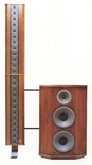 the center to center
distance as small as possible. The tweeters were mounted on a 10" wide
board. The width was selected to support the lowest frequency required of the
domes. A column of 25 could just fit between the floor and ceiling of our
listening room. The tweeters were wired in series-parallel. Ideally, the column
should be continuous without any spacing between the active tweeter diaphragms.
the center to center
distance as small as possible. The tweeters were mounted on a 10" wide
board. The width was selected to support the lowest frequency required of the
domes. A column of 25 could just fit between the floor and ceiling of our
listening room. The tweeters were wired in series-parallel. Ideally, the column
should be continuous without any spacing between the active tweeter diaphragms.
The results of the listening tests for the tweeter column was so positive with respect to imaging, depth and spaciousness, I decided to pursue this arrangement by adding a well-designed bass unit to go with it. In the initial phases of construction, we had the listening room and reverberant room to make measurements for the system.
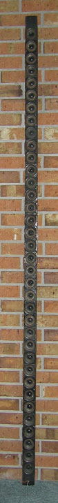
I had also made a column of 36 cone tweeters to use for comparison, shown at the left. These were the Peerless tweeters used in the ML-1C system. The column was 87-1/2” high and 2-1/4” wide. I was concerned about driver spacing in the column. The 36 tweeters had much closer diaphragm to diaphragm spacing, but did not have as high a power handling or as good dispersion. However, the effect of closer spacing did not make an audible difference compared to the dome tweeter spacing when I was back in the listening area. I had found earlier that flat diaphragm or continuous ribbon tweeters exhibited high distortion at high listening levels compared to 25 individual soft dome tweeters.
Before the design was completed, Carl and I moved into our new acoustics lab and our new full sized anechoic chamber was constructed. One of the first pieces of equipment I ordered was the Bruel & Kjaer turntable so that we could investigate the polar response of columns. A variety of test frequencies were selected. The column was placed on the turntable on its side or standing up and then rotated 360 degrees for both horizontal and vertical response. The continuous polar response curves were made automatically. This was very valuable to gain insight into the acoustic characteristics of a long and short columns with respect to tweeter spacing, mounting panel width, directionality, shape, and distance from the source, etc. I was able to find many relationships in measuring the column this way but I found that listening was still a very significant part of evaluating the columns. The mixed impression gathered from theory did not indicate how good the columns would sound.
Measurements in the listening room were also needed to show what was happening. The real time analyzer measurements confirmed what we had heard earlier. Since we tend to hear in 1/3 octave bands rather than narrow one-cycle bandwidths, 1/3 octave analysis with pink noise was in order. I found a simple but effective demonstration relating to the distance between the individual tweeters. The 1" dome columns were mounted in the normal floor to ceiling position on the listening room wall. By moving the microphone up, down and side to side in the listening area, the whole high frequency spectrum could be seen at once on the Bruel & Kjaer 3347 real time analyzer. It showed very smooth response throughout the listening area. It could also be heard to be very smooth. The only area where changes could be heard was within a foot or so from the column. This was not where any normal listening would be done. However, if the spacing between tweeters was increased, the interference or lobes from the individual tweeters would eventually extend out into the listening area. Measurement in the reverberant room showed that the total radiated power from the column was very constant with frequency.
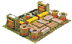
One of our dealers had an application that was very unique. It was for a disco. The columns were to be suspended horizontally overhead and the bass cabinets located against the walls. We set up a demo out in the warehouse with the columns facing down about 9 feet from the floor. By walking beyond the ends of the columns, all the highs could be heard to drastically decrease. This directional feature could provide plenty of highs directly over the dance floor but not in other areas where they were not wanted. The columns could be made longer to cover as much area as needed.
The tweeter column offered several advantages. Each tweeter could easily handle 10 watts of sine wave power at less than 0.3% distortion. Twenty five tweeters in a column provided a rating of 250 watts of program material at high frequencies and that was conservative. The high power handling also allowed for a low crossover frequency as well. Floor and ceiling reflections were drastically reduced and more accurate sound reproduction was achieved. The improved coherence of sound radiating from the same plane on the wall added even more realism.
The XRT20 was so unique, I was awarded a patent for this unusual column design. In addition to this patent, I shared a design patent for the construction of the system with Tom Rogers at McIntosh. Later, our research extended even further for short columns in the design of the XRT18. The last of my column designs was a triple column for the McIntosh XR290.
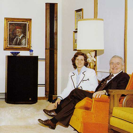
Gordon Gow was one of the first to include my design in his home. Here he is in his living room with his wife Palma. Gordon had a good ear for music and regularly attended concerts and the opera both in Binghamton and abroad.
![]()
The production tweeter column was constructed of sheet metal. It was made in two sections with walnut veneer and walnut end caps. Only 24 tweeters were used and a resistor was substituted for the 25th speaker. Ideally, the column should run from floor to ceiling, whatever the ceiling height happened to be. However, the production tweeter column was a little shorter than the prototype. This allowed space in homes where there might be baseboard heat and/or ceiling molding. The column was only 1-3/4" thick and was designed to be mounted on a wall with brackets. For some customers it was not possible to mount the tweeters on a wall. An optional stand was available that attached to the bass cabinet. The Philips tweeters were custom made for McIntosh. I specified a special undercoating that was not their standard production. This damped out a resonance that would otherwise be significant. The rectangular tweeter plates permitted close spacing between the domes.
The bass cabinet contained two 12" woofers and one 8" mid-range. Although the drivers were mounted only on the front panel, the grille covered the two angled faces as well. In early versions the two woofers handled the same frequency range. In later versions, the lower woofer went from 20Hz to 150Hz. The upper woofer went from 20Hz to 250Hz. The use of two different woofer crossovers reduced interference between the woofers in the upper bass where the distance between them was significant compared to 1/2 wavelength of the sound being radiated. The 8" mid-range was contained in a sealed enclosure and covered the range from 250Hz to 1500Hz.
The credenza shape of the bass cabinet was very acceptable in the home. In addition to presenting an attractive shape, the angled sides reduced reflections from the tweeter column when it was placed near the bass cabinet. They also provided some non-parallel interior cabinet surfaces to reduce standing waves. The angled faces on the tweeter column were made to match the bass cabinet and to reduce edge reflections.
Red and yellow indicator lights were mounted in the front of the bass cabinet at the bottom right. The yellow light was connected directly to the system input. It became visible when the input to the system approached rated power. It served only as a warning indicator. If the system was driven excessively hard, the main fuse would blow. If the system continued to be driven after the fuse blew, the yellow light would still be seen but no sound would be heard. The red light was connected directly across the tweeter fuse. It could only be seen if the high frequency fuse blew and the system continued to be driven at high power. Protection circuits were included for the lights.
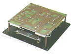 In Early versions, a printed circuit crossover board
was attached with spacers to the back of a large metal terminal plate for
connections in the rear. The crossover could then be removed from the rear of
the cabinet without removing any of the drivers.
In Early versions, a printed circuit crossover board
was attached with spacers to the back of a large metal terminal plate for
connections in the rear. The crossover could then be removed from the rear of
the cabinet without removing any of the drivers.
 In later versions, the crossover was mounted
internally in the cabinet and a smaller terminal plate was used. Laminated iron
core crossover coils were used for the woofer circuits. They had less than 1%
distortion at 600 watts. 120 Volt AC high current motor running capacitors were
used in the mid and tweeter circuits.
In later versions, the crossover was mounted
internally in the cabinet and a smaller terminal plate was used. Laminated iron
core crossover coils were used for the woofer circuits. They had less than 1%
distortion at 600 watts. 120 Volt AC high current motor running capacitors were
used in the mid and tweeter circuits.
By using the tweeter columns at the insides of an XRT20 stereo pair, the arrival time between the bass unit and the tweeter column was very satisfactory in the normal listening area. Also, a spacing of 8" was recommended between the edge of the tweeter column and the edge of bass cabinet. If the column was closer than 8", there could be reflections from the shallow sides of the bass cabinet. If the distance between the center of the bass cabinet and the center of the tweeter column was greater than 1 meter, the system could be perceived as two separate sound sources.
![]()
Japanese Award

The XRT 20 speaker system receives Japan's Grand Prix Award in 1982. The award is issued to Electori Co., Ltd. By Radio Technology Magazine.
![]()
|
|
|
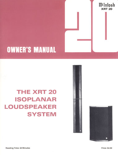
After the design was completed, the work was far from finished. I prepared a bill of materials for the entire system. The bill of materials was divided into subassemblies. If new parts were used, I wrote out a new part number request describing the part and the vendor. For the crossover subassembly, I made a pictorial layout of the board, including the location of the holes, where solder lugs were to be riveted. There was also a wire list specifying the wire size, color, lengths and connectors. If the drivers were made by McIntosh, a separate bill of materials was also included. The packing bill of materials was provided by engineering. I wrote the production test specifications for the crossover boards, drivers and finished systems. I also provided a sample wiring board for production. Production occasionally sent boards or drivers to the lab for testing if they were outside of the test of limits.
In addition to all of this, I was involved in writing the owner and service manuals. The owner’s manual contained a description of the design features and the system components. There was a brief description of the circuitry as well as the specifications. The service information contained schematic diagrams and pictorials of the crossover board. Specifications were also included.
There were often several printings of the owner’s manual. The cover appearance was sometimes changed and minor changes sometimes made to the text. There were sometimes changes made to the service information as well. If there was a change in the circuitry or parts, a new service information might be issued with the corresponding serial numbers indicated on the cover. If the changes were minor, a service bulletin was issued instead. Each issue of the manuals and bulletins could be identified at the back or on the bottom. For example, the back cover of this owner’s manual had the numbers 039-286.
![]()
I am pleased after all these years that my column solution to power handling and my patent has continued to be successfully marketed by McIntosh. It has been almost 30 years since I had constructed the first prototype. The advantages of the column in home systems are too good to ignore. See my page about my experience with columns.
![]()
XRT20 Specifications
Response: 20Hz to 20,000Hz
Power rating: 300 watts continuous, (500 watt occasional peak)
Output sensitivity: 89dB/watt/meter re: 8 ohms
Impedance: 8 ohms
Woofers: two 12" McIntosh
Mid-range: one 8" McIntosh
Tweeters: twenty four 1" custom soft domes
Crossover frequencies: 250Hz and 1500Hz
Overload protection: main and high frequency fuses
Finish: walnut
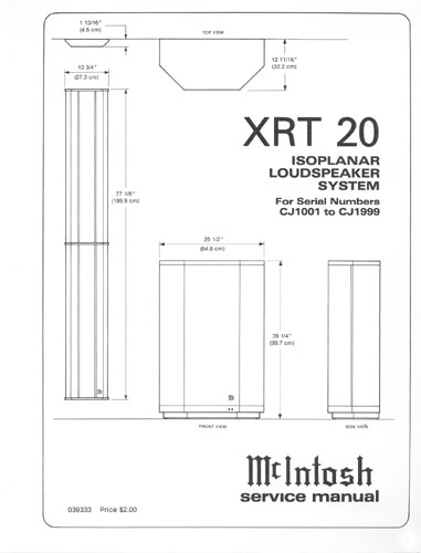
Dimensions: Bass section: 39-1/4" high, 25-1/2" wide and 12-11/16" deep
Dimensions: Tweeter column: 77-1/8" high, 10-3/4" wide and 1-13/16" deep
Weight: Bass cabinet and tweeter column 159 lb.
Sold from 1979 to 1985
Last retail price: $6600.00 /pair
CS20 Stand
Finish: Black
Shipping weight: 38 lb./pair
Last retail price: $500.00/pair
![]()
|
About This Site |
||
|
|
More text and pictures about McIntosh will be added as my research continues. Any comments, corrections, or additions are welcome. |
|
|
|
Created
by Roger Russell |
|