Published Articles by Roger Russell
These pages are copyrighted
No portion of this site may be reproduced in whole or in part
without written permission of the author.
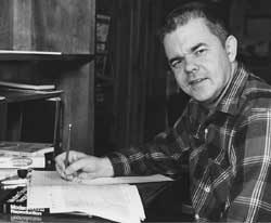
It was a lot of work in the early days to write articles. There were no computers and no word processing programs. It was literally cut and paste portions of the manuscript and adding or crossing out sections. When the changes became too much to manage, the whole thing had to be typed all over to make any sense out of it. After about seven go-arounds, it was ready to submit for publication.
![]()
 Build a Hi-Fi Volume Compressor-Expander
Popular Electronics October 1964 Page 41 [6 pages]
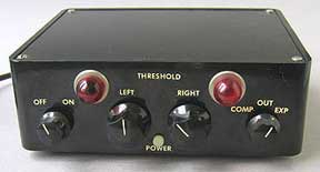
This was my first magazine article. A simple transistor circuit and lamp are connected at the power amplifier output. A photocell coupled to the lamp is connected at the power amplifier input. By switching the photocell in series or in shunt with a voltage divider, the device will expand or compress the audio signals. The high input impedance of the power transistor does not affect speaker performance when connected to the amplifier output terminals. DC balance controls allow adjustment so the lamps just extinguish when there's no input signal. Construction is described for use with a stereo power amplifier. The photo shows the front of the expander-compressor. The DC balance lights are at the top. The power switch is at he left. The input level controls are in the center and the compress/expand/out switch is at the right. A power indicator light is at the bottom center. It works just as good today as it did back in 1964. Here’s the front view. For a more detailed history, see my page about the history of this compressor-expander.
Julian Hirsch even wrote a brief review at the end of the article "...there was no high frequency loss. The unit was easy to install and adjust, and did all that could be expected. Well planned and constructed..."
 Build a Hi-Fi Volume
Compressor-Expander
Build a Hi-Fi Volume
Compressor-Expander
Electronic Experimenter's Handbook 1965 Fall Edition Page 51 [7 pages]
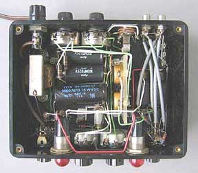
The Popular Electronics article was a favorite with readers and it was selected as one of the articles to appear in the quarterly Electronic Experimenter's Handbook next fall. I added a description for a single channel compressor-expander as well. I received payment again for this article. The photo shows the rear of the expander-compressor.
The input and output jacks are at the right side. The DC balance controls are in the center and the fuse and line cord are at the left.
Here is a top view of the stereo version showing the wiring. The cabinet is plastic and some shielding was used on the bottom to keep any hum or noise completely inaudible.
![]()
 Enclosures for
High-Compliance Loudspeakers
Enclosures for
High-Compliance Loudspeakers
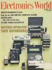
 Electronics world August 1966 Page 25 [5 pages]
This article was written while I was an engineer at the Sonotone Corporation. It described the procedures on how to measure high compliance woofer characteristics and how to select the appropriate cabinet size without the need for building a test cabinet. I plotted the multiple design curves by hand using the equations for mass, compliance, etc. It was based on my work in designing the Sonotone RM speaker series using 4", 6" and 8' woofers.
The photographer that Sonotone used for their advertising took the photos. Later, reprints of the article and glossy photos were used by the sales department for advertising the RM-0.5, RM-1 and RM-2 systems. The picture at the right is the RM-2 system.
![]()
 Speaker Evaluation: Ear
or Machine (part 1)
Speaker Evaluation: Ear
or Machine (part 1)
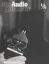
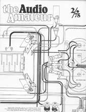
Audio Amateur issue 1/75 Page 10 [6 pages]
I took this cover photo on the left with my hand holding a General Radio sound level meter. A speaker is in the background, but doesn't show up in this image.
This is a very detailed two-part article on how to evaluate speaker systems. Various listening techniques are discussed including listener bias as a factor in the results. I even incorporate some general semantics approaches about perception. Simple and then more complex and expensive measurements are described. Procedures are outlined for measuring response, harmonic distortion, intermodulation distortion and impedance. Room acoustics and preferred speaker response characteristics are also discussed.
 Speaker Evaluation: Ear or Machine (part 2)
Audio Amateur issue 2/75 Page 20 [7 pages]
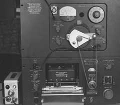
In this article I offered to calibrate microphones that readers could send in so they could make relatively inexpensive measurements at home. I calibrated quite a few microphones that year. Calibration was from 20 to 20kHz, or as far as the microphone would respond. I used the substitution method by comparing with my Bruel & Kjaer 4133 condenser microphone. This test was similar to the way we tested microphones where I worked at the Sonotone Corporation.
The picture at the right is part of my General Radio test equipment that I used for the article. There are many other photos and graphs in the article. Although this article was written many years ago, the tests are still just as valid. However, acoustic test equipment has greatly improved over the years
![]()
 Time Compensated Hi-Fi System
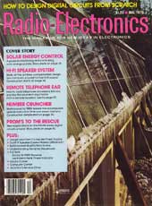
Radio-Electronics December 1978 Page 38 [5 pages]
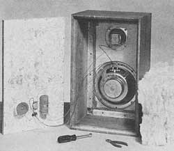
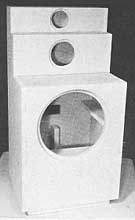
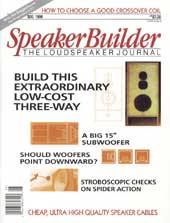
This is a construction project. The average acoustic centers of the drivers in this three-way system are all aligned in the same vertical plane. This results in a stepped back arrangement for mounting the mid and tweeter. The design allows greater coherence and smooth response for the system. Detailed instructions and diagrams for the cabinet and crossover are given, including how to make your own crossover coils.
The speakers were made by Norelco and were commonly available at the time. There was a 12" woofer, a 2" soft dome mid and a 1" dome tweeter. I supplied the photos of the various cabinet construction steps and the crossover construction. A year later I sold the systems and moved on to newer designs.
![]()
 Put Wasted Space
in Reach-Build an Attic Railroad
Put Wasted Space
in Reach-Build an Attic Railroad
 Popular Science
April 1985 Page 118
Popular Science
April 1985 Page 118
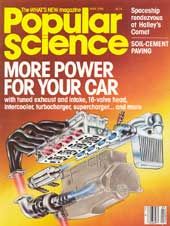
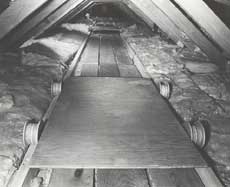
When the center of the roof is only 30" from the attic floor, it's hard to get around up there. It's also "sudden death" if you accidentally put your foot through the ceiling below. By installing 2X4 rails spaced two feet apart, and a flat carriage with wheels, you can lay on your back and pull yourself from one end of the house to the other. If you put shelves on the joists on either side, you can store items that aren't affected by heat or cold. I gained 110 feet of shelf space this way. In my photo on the right you can see one of the carriages and the fiberglass insulation on either side of the rails.
![]()
 Quality Issues in Iron Core Coils
Speaker Builder issue: six 1996 Page 44 [9 pages]
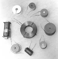
Many people use iron core coils in their crossovers, but don't really know how good they are. Sometimes the speaker can get the blame for bad sound when all the time it could be a poor quality iron core. This article describes how to measure coil distortion as well as conduct an effective listening test. The sample group of coils tested in this article yielded a wide range of results.
The article was based on my test setup at McIntosh lab to select low distortion cores for our crossover coils. Several iron cores were exceptionally good, even up to 600 watts, and a few were bad, even at 15 watts. The center coil in the picture is an air core coil I used for comparison and acted as a double check on my test equipment. The others are various iron core coils I purchased and tested for this article. I plotted graphs of power versus distortion at several different frequencies for each coil. All of the coils were 5 mH for this article.
![]()
 Etalage and Rex
Cole Mystery Clocks
Etalage and Rex
Cole Mystery Clocks
 NAWCC Bulletin
(National Association of Watch and Clock Collectors) October 2002 Page 571 [6
pages]
NAWCC Bulletin
(National Association of Watch and Clock Collectors) October 2002 Page 571 [6
pages]
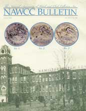
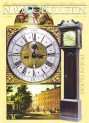
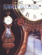
The mystery is how the hands are driven without any visible means. Several clocks made by Jefferson Electric have a patent number 2,642,713 on the clock. However, the clock described in the patent was made by Etalage Reclame Corporation of New York. The patent was awarded to Leendert Prins, Bilthoven, Netherlands, in 1953. Jefferson apparently bought the rights to the patent.
The Etalage Magiclock and Rex Cole mystery clocks are also described in this article. These were made based on earlier patents also awarded to Leendert Prins.
![]()
 Mastercrafters and Haddon Mystery Clocks
NAWCC Bulletin (National Association of
Watch and Clock Collectors) August 2003 Page 419 [6 pages]
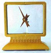
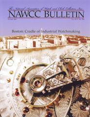
My earlier article describes clocks that have one or more rotation clear discs, with hands attached to the center. They are driven by a gear or gears attached to the perimeter of the glass and are driven in turn, by a motor in the base. This article explains about hands attached in the same way but where the glass is not round and cannot rotate. So how are the hands made to move?
The Mastercrafters model 209 "Fantasy" and the Haddon "South Wind" mystery clocks are described in this article.
 The “Dutch Secret” and
Jefferson Electric Clock History
The “Dutch Secret” and
Jefferson Electric Clock History
NAWCC Bulletin (National Association of
Watch and Clock Collectors) October 2004 Page 600 [6 pages]
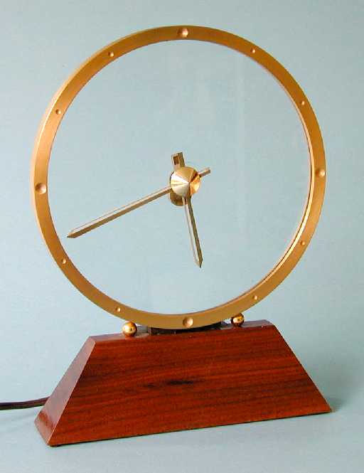
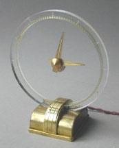
The Dutch Secret may be the clock that inspired the president of Jefferson Electric to create the first of their clocks, the Golden Hour. The Golden Hour was sold essentially unchanged for 41 years starting in December of 1949. I also describe the history of Jefferson Electric and all the other clocks that they made over the years.
The Dutch Secret is unique in that the ring is made of Plexiglas and is illuminated by a light in the base. It was made in Holland, perhaps in the late 1930’s or early 1940’s, and operates on 240 volts and 50 Hz house current.
![]()
 Radium and the Dial Painters
NAWCC Bulletin (National Association of Watch and Clock Collectors) October
2005 Page 577 [6 pages]
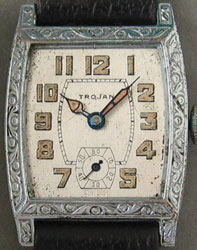
Radium paint was used on many different articles starting in the 1920’s and going on for several decades. Watch and clock dials were very common back then but the dial painters suffered from ingesting the radioactive paint from the required process of lip-pointing.
A history of radium and the paint manufacture is included with measurements of several radioactive sources. The units for radiation exposure should be in mrem and not mR. However, the values are correct. The units and values for the measurements in mR are correct.
![]()
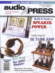 A Unique Stereo Column System
audioXpress magazine November 2005 Page 20 [10 pages]
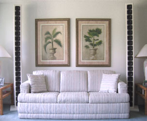
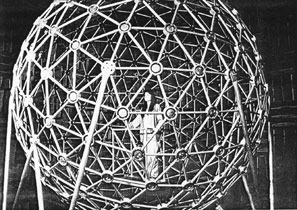
This column produces a new listening experience for stereo imaging and extended bass. No crossovers are used and electronic equalization corrects for response. Twenty 4-inch drivers provide high power handling and by putting them in the same long vertical column, outstanding coherence is heard. It is based on two of my earlier patents.
The exceptional performance led to investing in a system having even smaller and much more expensive drivers that are of higher quality.
![]()
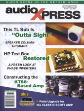 Upgrading a Unique Stereo
Column System
Upgrading a Unique Stereo
Column System
audioXpress magazine July 2006 Page
26 [10 pages]
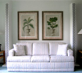
A revised version of the system includes more expensive drivers, smoother response, lower distortion, a protective network, angled cabinet sides and a grille. Twenty five 3-1/2” drivers are used that have more than twice the cone excursion and a copper pole piece in the gap, reduces distortion contributed by the magnet structure by a factor of 10. .
The listening quality of the earlier column was very good but this new column goes beyond excellent. The results were so good that I decided to market the system with a professionally made cabinet and grille assembly and include a custom made equalizer. This became known as the IDS-25 Stereo Loudspeaker System.
![]()
 Sounds and Hearing
(Part 1)
Sounds and Hearing
(Part 1)
 audioXpress magazine October 2007 Page 28 [6 pages]
The first part is about how we hear music. Considering all the time and effort audiophiles spend producing such a wide variety of amplifiers, speakers and other devices, the hearing process is just as important as any other part of the music reproduction chain—from the recording to the ear mechanism and nerve impulses sent to the brain to be interpreted.
Many people take the hearing process for granted and awareness of sound location and frequencies are only in the background of our attention. Understanding how we hear can provide more appreciation and enjoyment even for everyday sounds.
![]()
 Sounds and Hearing (Part
2)
Sounds and Hearing (Part
2)
audioXpress magazine November 2007
Page 32 [4 pages]
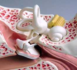
The second part is about ear intricacies and how you hear. The ear is a biological transducer transforming acoustical energy into mechanical energy and then to electrical pulses. A detailed process for hearing is described including a picture and several diagrams.
There are safety devices in the ear but they can be overridden to cause hearing damage. There is an emotional appeal to loud music but care must be taken to avoid permanent hearing damage
![]()
|
About This Site |
||
|
|
More of my magazine articles will be added as they are published. Any comments, corrections, or additions are welcome. |
|
|
|
Created
by Roger Russell |
|