The C26 Stereo Solid State Stereo Preamplifier
Plus the C27 Preamp
and the MX112 and MX113 Tuner-Preamps
by Roger Russell
These pages are copyrighted
No portion of this site may be reproduced in whole or in part
without written permission of the author.
![]()
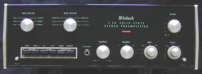
 In 1967, I began design of the C26 preamp. It replaced
the C24. This was the first preamplifier to have an all glass front panel,
which matched the new MC 2505 power amplifier. It was assigned a project number
of P 216. The requirements had already been determined by Gordon Gow, based on
his marketing research.
In 1967, I began design of the C26 preamp. It replaced
the C24. This was the first preamplifier to have an all glass front panel,
which matched the new MC 2505 power amplifier. It was assigned a project number
of P 216. The requirements had already been determined by Gordon Gow, based on
his marketing research.
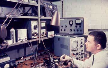
Here I am at my test bench with my first McIntosh project. Initially I used a C24 chassis as the first prototype. My bench equipment consisted of a Hewlett-Packard 330B distortion analyzer, a Hewlett-Packard 200CD oscillator, a Hewlett-Packard AC voltmeter, an RCA Senior Volt-Ohmist and a large Tektronics scope. The electrical maintenance section periodically calibrated all of the engineering and production test equipment.
Some of the circuitry was already being used in the MAC 1700 receiver, but I revised several features and added several new ones. New circuit boards were laid out and were etched in the model shop. All response measurements for the tone controls, filters and loudness control were plotted by hand on graph paper. Distortion measurements at each frequency were made by carefully tuning the HP 330B to null out the fundamental. The 330B was also used to measure output noise and hum.
Turn-on and turn-off thumps had to be eliminated. Otherwise, any transients in the circuitry could be heard if the power amplifier remained on and the C26 was turned on or off. The power supply was voltage regulated. A 75V zener diode and power transistor controlled the voltage. Cable capacity was a problem at high frequencies for some shielded wires to the loudness and balance controls. I used a driven shield. Instead of connecting the shield to ground, it was connected to 36 volts at the emitter of the following amplifier stage. This solved the problem.
The dual concentric tone controls were 11 position switches. Resistors having 5% tolerance were used throughout. The center positions were electrically flat and were easy to return to. Color-coding was used throughout the preamp. The solid colors were for the left channel and the colors with the white stripes were for the right channel.
After the initial design was finished, a complete P216 prototype was made including an illuminated glass front panel. Four lamps were used to illuminate the glass panel. To insure uniform lighting of the panel, a 1/8” thick plastic panel was used behind the glass. White paint was used on the plastic for areas where light was needed to shine through corresponding areas of the glass. The plastic panel was designed in engineering. The panels and silk screening were made in the production facility. A rectangular steel can was used to house the power transformer. An optimum orientation for the transformer in the can was determined for minimum hum pickup. The transformer was then encased in potting material. A 5.3V winding in the power transformer provided for the 6.3V #1866 lamps used to illuminate the front panel. The lower voltage extended the life of the lamps.
The brass control shafts all had special grounding springs to insure freedom from electrical noise. The power switch was part of the volume control. A length of flexible shielding was run from the AC outlets in the rear to the front for the switch wires. A shield was also placed over the AC switch contacts at the volume control to insure that there would be no hum pickup.
I designed the input selector switch from a new series made by CTS in Kentucky. The first sample was made in the lab until production samples arrived. Bill Scrivner, head of purchasing, and I visited CTS to check out their facilities and see what could be done to improve the tracking of the stereo volume controls in the -60dB area. The factory was amazing. It was geared for incredible quantities. The plating process handled 30-gallon containers of volume control covers at one time. The automated assembly machines dispensed a finished control about every second. Some machines ran 24 hours a day. I wondered where all those controls could possibly be going.
My C26 prototype was sent to production as the wiring sample. The first input selector switches had not yet arrived and we were scheduled to start production. I flew out to South Bend, Indiana and drive over to Elkhart to pick up several hundred of the switches and was back the same day. C26 serial numbers started with 10P01.
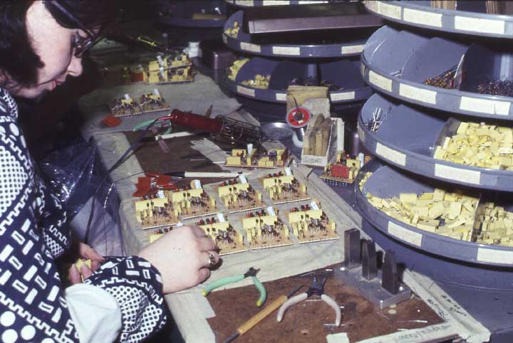
This picture is from 1968. The production boards are being assembled. The parts are being inserted by hand. Round rotating trays holding the various parts can be seen at the right.
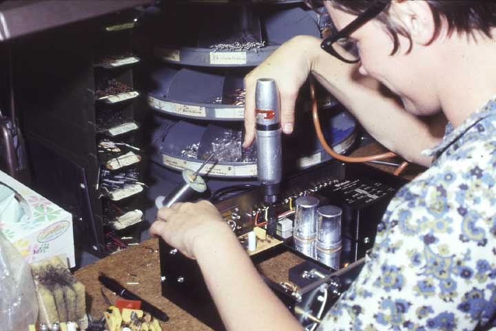
Final assembly is done here. The power supply board is being screwed in place. The C26 phono section had an orange module that contained several parts inside and can be seen near the bottom left of the picture.
![]()
![]()
Speaker connections and switching
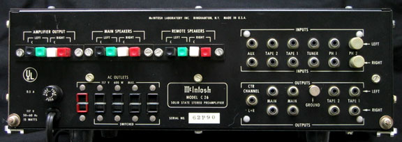
Two sets of stereo speakers could be switched at the front panel of the C26. The connecting push type terminals were on the rear panel at the left side. There were three sets. Each set was color coded to make connecting as easy as possible. Black was left common; green was left positive; white was right common and red was right positive. The left set connected to an external power amplifier output. The center set went to the main speakers and the right set went to the remote speakers.
There was no headphone amplifier in the C26. Instead, the headphones could be driven by the speaker signal when an external power amplifier was connected to the rear of the preamp. Protective resistors were used in series with the headphone jack. Stereo headphones could then be plugged into the stereo jack at the front panel. The power amplifier output had to be connected to the rear terminals of the C26 for the headphones to work. Two 25 ohm 25 watt power resistors were mounted on heat sinks inside the C 26. They served as amplifier loads if both speakers were switched off and headphones were used.
![]()
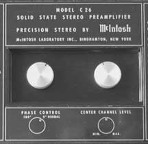 Two unique features in the C26 were the phase switch
and the center channel output. These switches were located in a recess at the
top of the C26 at the front. The phase switch reversed the phase of one
channel. It was a quick and easy check to tell if the speaker connections were
properly phased. Stereo imaging and overall sound was not good if one channel
was out of phase.
Two unique features in the C26 were the phase switch
and the center channel output. These switches were located in a recess at the
top of the C26 at the front. The phase switch reversed the phase of one
channel. It was a quick and easy check to tell if the speaker connections were
properly phased. Stereo imaging and overall sound was not good if one channel
was out of phase.
The center channel output was at the rear of the preamp and the level control was at the top. At the time, it was recommended that the center channel be run at 6 dB below the output of the right or left channels.
The center channel was a simple mixing circuit derived from the left and right channels. At the time, a center channel was publicized by Paul Klipsch as a sonic enhancement. Also, Mercury Living Presence records were made using an additional center channel microphone.
![]()
Continuously Variable Loudness Control
The loudness control supplied low frequency boost to compensate for the behavior of the human ear at low listening levels. Most loudness contours were switched in with a fixed amount of contour using a tap on the volume control. The user had no control of the contour for any particular volume control setting. The C 26 had much better compensation. It provided a continuously variable contour. First, the volume was set at the highest desired listening level. Then, when the loudness control was rotated clockwise from the flat position, the volume decreased and the contour automatically increased the required amount of bass amplitude and bandwidth for the new listening level. This action provided full frequency range listening at even the lowest listening levels.
![]()
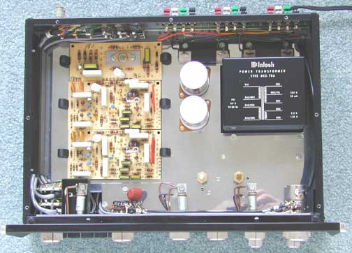
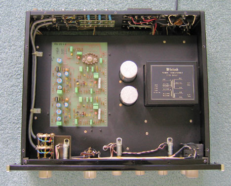
Here’s the view with the top cover removed. The top of the chassis was shiny chrome. Three circuit boards can be seen at the left. They are held in place with 2 clamps that can be seen on either side of each board. The filter capacitors can be seen at the center and the power transformer is at the right rear. A schematic diagram of the transformer is silk screened on the top of the can. The 25-watt power resistors are located behind the transformer. They are held against the chassis with metal brackets. The rear board contains the power supply and center channel circuits. The regulator transistor can be seen mounted on a rectangular heat sink. The left and right circuit boards are toward the front.
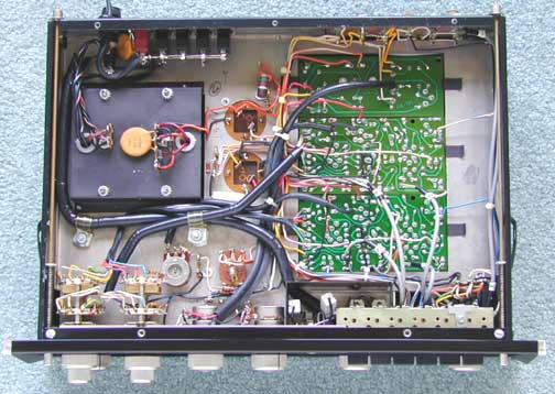
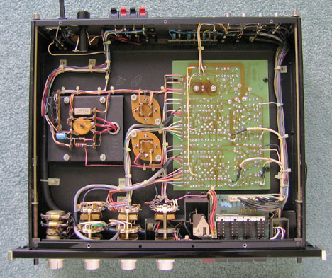
Here’s the view with the bottom cover removed. The transformer is at the upper left with terminal strips for the rectifier diodes and a yellow 1400-volt line filter capacitor. The tone control switches are at the bottom left and the pushbutton switches are at the bottom right. The circuit boards are coated with green resist material so that solder does not coat all of the copper on the entire printed circuit material—only where the components come through. This avoids wasting solder in non-essential areas. The large black tubes are actually insulated shields that cover the wires from one part of the preamp to the other.
I purchased this particular C26 several years ago and it was not working. I found that the original 1 amp fuse had been replaced with a 3-amp fuse and the power transformer was burned out. New transformers were no longer available but I remembered I had a sample transformer in my parts box that I had saved. I used the oven in the kitchen to unpot the tar in the transformer case and replaced it with the sample. Before turning the preamp on, I checked the power supply and found the power supply diodes were shorted. After replacing these and verifying everything else was ok, I turned it on and it now works fine. When replacing the diode, I found that someone had unsoldered a few wires in the power supply to diagnose the problem and the seller probably knew the transformer was bad.
This is what happens when there is a problem and a fuse is blown and then replaced with a larger one. The preamp should have been brought into a service center to find the cause. As a result, the owner lost the whole preamp because of a couple of 30 cent diodes.
The C26 preamp left and right channel circuit boards were also used in the MX112, MX113, MX114 and MX115 tuner-preamps. They were not combined into a single board because each board was mounted vertically to save space on the chassis.
|
|
|
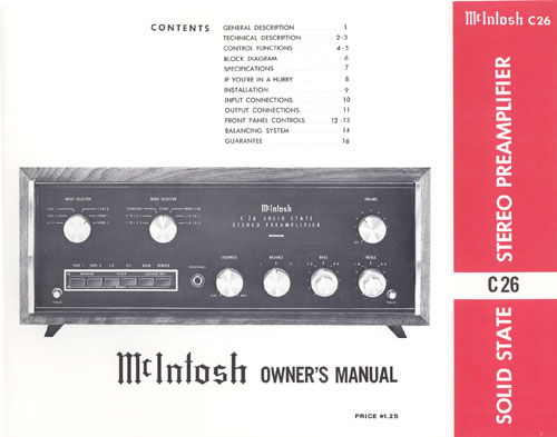
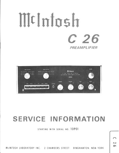
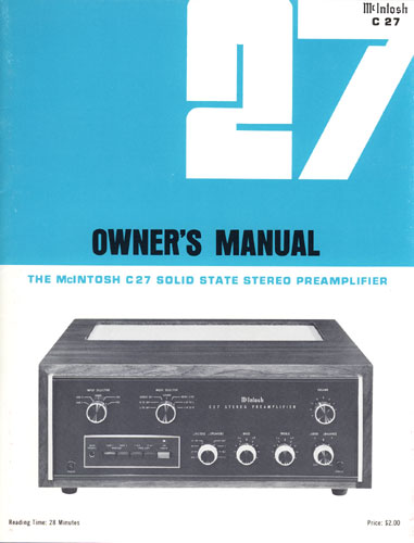
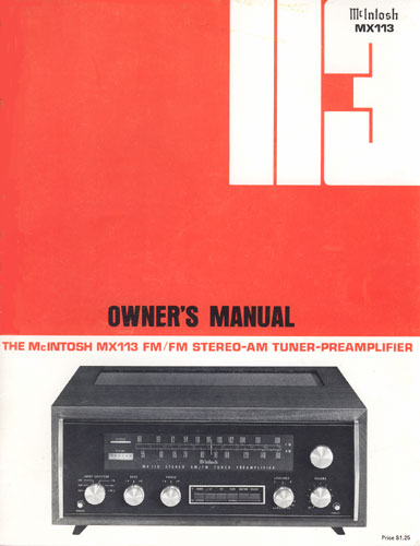
In addition to the design work, I was also involved in writing the owner and service manual. The owner’s manual explained how to use the controls and switches and what they did. There was a brief description of the circuitry as well as the specifications and performance curves. It also explained how to make connections to a system including the speaker switching terminals. The service information contained schematic diagrams and pictorials of the circuit boards plus voltage readings. Specifications were also included. Besides all of this, I also prepared test procedures for the production people.
There were often several printings of the owner’s manual. The cover appearance was sometimes changed and minor changes sometimes made to the text. There were sometimes changes made to the service information as well. If there was a change in the circuitry or parts, a whole new service information might be issued with the corresponding serial numbers indicated on the cover. If the changes were minor, a service bulletin was issued instead. Each issue of the manuals and bulletins could be identified at the back or on the bottom. For example, the back cover of this owner’s manual had the numbers 038-224
![]()
Response: +0 -0.5 dB 20 to 20,000Hz
Distortion: less than 0.1%
Input sensitivity: 2.0mV phono. 0.25V aux, tape and tuner
Input impedance: 47k phono. 250k aux, tape and tuner
Hum and noise: -74 dB below 10mV input phono. -85 dB aux tape and tuner re:
2.5V
Output main: 2.5V (10V max)
Output center channel: follows main output
Output impedance: 200 ohms into 47k or higher
Output impedance center channel: 1200 ohms into 47k or higher
Voltage amplification: 20dB aux, tape and tuner. 62dB phono
LF filter: 50Hz 6 dB/octave. Down 12 dB at 20Hz
HF filter: 5kHz 6 dB/octave. Down 12 dB at 20kHz
Bass controls: switched 11 position dual concentric -20 dB to +16 dB at 20Hz
Treble control: switched 11 position dual concentric -20 dB to +20 dB at
20,000Hz
Loudness control: flat response or continuously variable
Balance control: full left to full right
Input selector: Aux, Tape 2, Tape 1, tuner, Phono 1, Phono 2
Mode selector: L to L&R, R to L&R, stereo reverse, stereo, mono, mono
L, mono R
Phase control: 0° or 180° in the left
channel. (top of Chassis)
Center channel level control: (+ or — 6 dB with center channel control at top
of chassis)
Semiconductors: 18 silicon planar transistors, 3 silicon diodes
Speaker Switches: Main and Remote
AC outlets: 4 switched, 1 unswitched
Tape monitor: Tape 1 or Tape 2 with interlock
Panloc mounting
Front panel: glass, gold/teal, illuminated
Size: 5-7/16” high, 16” wide and 13” deep
Weight: 18 lb.
Sold from 1968 to 1977
Last retail price: $449.00
![]()
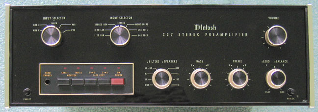
My work after the C26 and MX112 was in speakers. The update of the C27 was done by engineering and I was not involved with it. However, I was pleased to see that my design of the C26 remained essentially unchanged. However, some of the front panel arrangements were moved around. One improvement was the addition of a better tracking volume control that was not available for the original C26 design. Because the new control was not available with a power switch, power was controlled with the red push button switch instead. The knob styling was changed for a new look to match other newer McIntosh equipment. The speaker and filter switches were moved from the pushbutton location to share a concentric rotary switch. Tape copy switches were then moved to the pushbutton section. The loudness and balance controls were made concentric. The phase switch was eliminated along with the center channel output control but the center channel output jack remained.
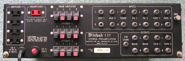
The speaker connections and switching are the same as the C26 but the terminals were updated for easier use. Two aux inputs are provided instead of one in the C26
Top View
Although the circuitry of the preamp remained essentially the same, the three boards used in the C26 boards were combined into a single board. Also, some transistors were no longer available and newer improved ones were substituted, resulting in some changes to associated circuit parts—resistors, etc. The new transistors also allowed for slightly improved distortion and lower noise. Light emitting diodes were added above the push switches.
Bottom View
A small printed circuit board was made for each light emitting diode and was located at the push button switches. A plug was used to connect this circuit board to the rear jacks. The small board at the input jacks was for DC blocking capacitors at the preamp input. After many years of use, a brown area on the circuit board can be seen that was caused by heat from the voltage regulator transistor. This occurred despite the use of a heat sink on the other side of the board. No damage was done as the board was made of fiberglass epoxy.
The C27 sold from 1977 to 1983. All together, the C26 design essentially lasted from 1968 to 1983 or 15 years. Both the C26 and C27 work as well today as they did when they were new.
|
|
|
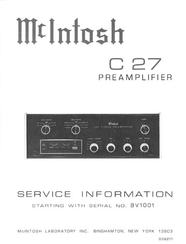
I was not involved with writing these manuals. However, much of the text was based on what I had written for the C26. As in the C26 manuals, there were often several printings of the owner’s manual. The cover appearance was sometimes changed and minor changes sometimes made to the text. There were sometimes changes made to the service information as well. If there was a change in the circuitry or parts, a whole new service information might be issued with the corresponding serial numbers indicated on the cover. If the changes were minor, a service bulletin was issued instead.
The C27 received a 4-page review in Audio magazine in September 1978.
![]()
Response: +0 -0.5 dB 20 to 20,000Hz
Distortion: less than 0.05%
Input sensitivity: 2.0mV phono. 0.25V aux, tape and tuner
Input impedance: 47k phono. 100k aux, tape and tuner
Hum and noise: -80 dB below 10mV input phono. -85 dB aux tape and tuner re:
2.5V
Output main: 2.5V (10V max)
Output center channel: follows main output
Output impedance: less than 1k ohms into 22k or higher
Output impedance center channel: 1200 ohms into 22k or higher
Voltage amplification: 20 dB aux, tape and tuner. 62 dB phono
LF filter: 50Hz 6 dB/octave. Down 12 dB at 20Hz
HF filter: 5kHz 6 dB/octave. Down 12dB at 20kHz
Bass controls: switched 11 position dual concentric -17dB to +16dB at 20Hz
Treble control: switched 11 position dual concentric -20dB to +20dB at 20,000Hz
Loudness control: flat response or continuously variable
Balance control: full left to full right
Input selector: Aux 1, Aux 2, Tuner, Phono 1, Phono 2
Mode selector: L to L&R, R to L&R, stereo reverse, stereo, mono, mono
L, mono R
Semiconductors: 18 silicon Planar transistors, 4 silicon diodes and 4 led’s
Speaker Switches: Main and Remote
AC outlets: 4 switched, 1 unswitched
Tape monitor: Tape 1 or Tape 2
Tape Copy: Tape 2 to Tape 1, Tape 1 to tape 2
Panloc mounting
Front panel: glass, gold/teal, illuminated
Size: 5-7/16” high, 16” wide and 13” deep
Weight: 20 lb.
Sold from 1977 to 1983
Last retail price: $749.00
![]()
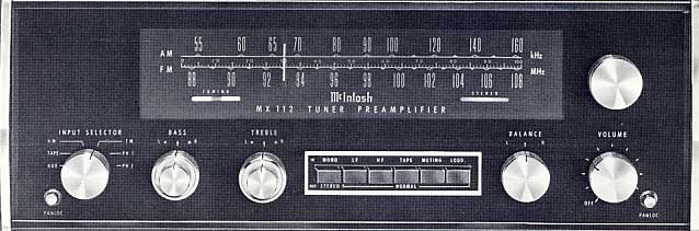
Meanwhile, the MX112 tuner-preamplifier was being designed. I was requested to incorporate a simplified version of the C26 to be the preamp section. The circuit boards were the same but some items like the speaker switches and center channel control were not used. A center channel output and a phase switch were located at the top. The loudness control was replaced by a fixed contour switch. The circuit boards were mounted vertically. Variable tone controls were used instead of the switches used in the C26. Because there was no detent for the center position, the controls had to be set by eye to be in the flat position. Instead of the seven-position mode selector switch in the C26, a mono-stereo switch was provided instead.
|
|
|
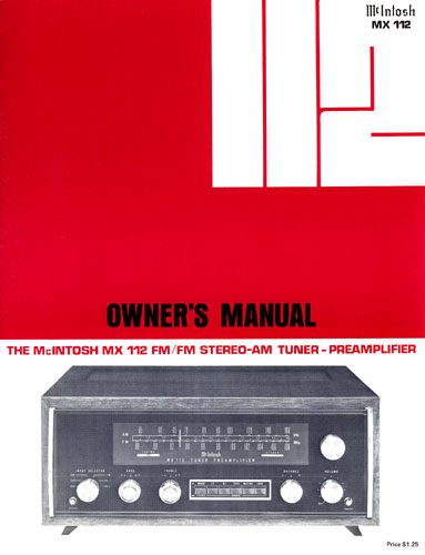
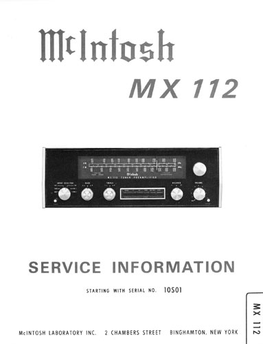
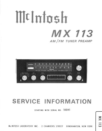
In addition to the audio design work, I was also involved in writing the audio portion of the owner and service manual. The owner’s manual explained how to use the controls and switches and what they did. There was also a brief description of the circuitry as well as the specifications and performance curves. The service information contained schematic diagrams and pictorials of the circuit boards plus voltage readings. Specifications were also included. Besides all of this, I also prepared audio test procedures for the production people.
There were often several printings of the owner’s manual. The cover appearance was sometimes changed and minor changes sometimes made to the text. There were sometimes changes made to the service information as well. If there was a change in the circuitry or parts, a whole new service information might be issued with the corresponding serial numbers indicated on the cover. If the changes were minor, a service bulletin was issued instead.
![]()
MX112 Preamplifier Specifications
Response: + or -0.5 dB 20 to 20,000Hz
Distortion: less than 0.1% at 2,5 volts output
Input sensitivity: 2.0mV phono. 0.25V aux and tape for 2.5 volts output
Input impedance: 47k phono. 250k aux and tape
Hum and noise: phono 70dB below 10mV input; equivalent to less than 3
microvolts at the input. 85dB aux and tape for 2.5 volts output.
Output main: 2.5V (10V max)
Output center channel: follows main output
Output impedance: 200 ohms into 47k or higher
Output impedance center channel: 1200 ohms into 47k or higher
Voltage amplification: to main output 20 dB aux, 0 dB to tape output
Voltage amplification: to main output 62 dB, to tape output 42 dB
LF filter: 50Hz 6 dB/octave. Down 12 dB at 20Hz
HF filter: 5kHz 6 dB/octave. Down 12 dB at 20kHz
Bass controls: variable dual concentric -18 dB to +16 dB at 20Hz
Treble control: variable dual concentric -20 dB to +20 dB at 20,000Hz
Loudness: fixed contour switch
Balance control: full left to full right
Input selector: Aux, Tape, AM, FM, Phono 1, Phono 2
Mode: Mono or stereo
Phase control: 0° or 180° in the left
channel. (top of Chassis)
AC outlets: 2 switched, 1 unswitched
Tape monitor: Tape switch
Panloc mounting
Front panel: glass, gold/teal, illuminated
Dial scale light intensity switch on top panel
Transistor complement: 4 jnction FET, 4 MOS FET, 27 silicon planar transistors,
2 integrated circuits, 20 diodes
Size: 5-7/16” high, 16” wide and 13” deep
Power requirements: 117 volts, 50/60 Hz, 30 watts.
Weight: 25 lbs. net
Sold from 1968 to 1971
Last retail price: $599.00
MX112 FM Tuner Specifications
Usable sensitivity: 2.5 microvolts at 100%
modulation for less than 3% total noise and harmonic distortion.
Response: + or – 1dB from 20 Hz to 15 kHz with standard de-emphasis and 19 kHz
pilot filter.
Harmonic distortion: Mono—0.5% at 100% modulation.
Image rejection: 75 dB at 100 MHz, 70 dB at 105 MHz
Spurious rejection 90 dB IHF
Capture ratio 1.8 dB
Drift 25 kHz at an ambient temperature of 25 degrees C.
Hum and noise: 65 dB at 100% modulation
Tuning indicator: 6HU6 electron ray for simple accurate center of channel
tuning
Stereo indicator: Stereo light activated by 19 kHz carrier only.
Muting adjust on top of panel
MX112 AM Tuner Specifications
Sensitivity: 12 microvolts at 1000 kHz using
external antenna input
Signal to noise ratio: 55 dB
Harmonic distortion: 1% at 30% modulation
Response: down 6 dB at 5000 Hz and 34 dB at 10 kHz
Selectivity: 10 kHz at -6 dB
Image rejection: 60 dB at 1000 kHz
![]()
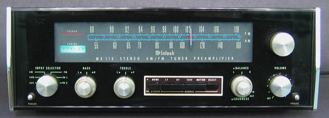
The MX113 was very similar to the MX112 but with several improvements. One of the nicest improvements was the addition of a selector switch for wide or narrow tuning. Although it was great when listening to AM, it also proved very helpful to sort out stations in a crowded FM band. Another addition was the SCA filter that reduced interference from the sub-carrier music broadcast by some FM stations. This music was commercial free and was sold to subscribers such as offices and stores. I remember building an SCA adapter but found the music very bland and frequency bandwidth limited, as it should have been for that purpose.
|
|
|
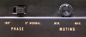
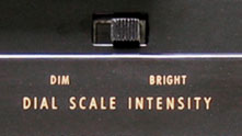
The audio section still retained the 0 and 180 degree phase switch. At one time this was useful in checking the correct wiring for stereo speakers or program material, which seemed to be important at that time but was soon discontinued. The switch is connected in the left channel. A muting control was also provided. When the mute button on the front panel was pushed in, FM inter-station hiss could be reduced and even eliminated. It could be adjusted with this control. The dial scale intensity switch was on the top panel also and could be set for dim or bright.
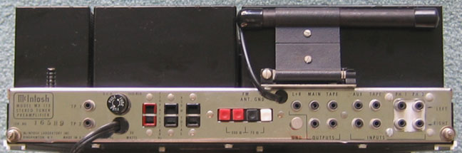
Another helpful feature was the AM ferrite antenna that could swing down and also be unclipped at one end and rotated for optimum reception. A center channel (L+R) output is provided but there is no level control. If the center channel feature was used, the level could be adjusted at the power amplifier. Another feature was the TP1 and TP2 outputs at the left side in the picture.. These could be connected to the MI3 or MPI4 to display multipath distortion for FM reception. The TP1 output was ahead of the FM de-emphasis network and on inter-station hiss, had the same spectrum as white noise.
Top View
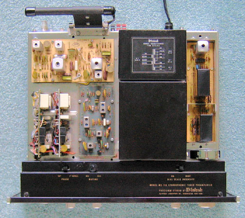
The top and bottom covers were removed for the pictures. Of course, the reason that I have made a detailed description of the MX113 is that it incorporates the C26 left and right channel circuit boards. They were not combined into a single board because they stood vertically and can be seen in the picture at the lower left corner of the MX113 chassis. This saved space on the main chassis. However, a hum problem was encountered because of the positioning of the boards. I found it was due to circulating currents in the cassis. I had to cut a long slot in the chassis between the boards to get rid of it. To the right of the audio boards is the AM board. Above them is the FM multiplex board. On the right side is the FM IF board. The tuning capacitor is located under the large black cover.
![]()
Bottom View
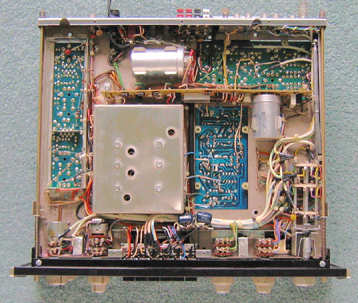
The power supply board is located on its side near the rear. It also contains the AGC filter and center channel sections. The input selector switch is at the lower right.
|
|
|
MX113 Preamplifier Specifications
Response: + or -0.5 dB 20 to 20,000 Hz
Distortion: less than 0.1% at 2.5 volts output
Input sensitivity: 2.0 mV phono. 0.25 V aux and tape for 2.5 volts output
Input impedance: 47k phono. 250k aux, tape and tuner
Hum and noise: 70 dB below 10mV input phono; equivalent to less than 3
microvolts at the input. 85 dB aux and tape for 2.5 volts output
Output main: 2.5V (10V max)
Output center channel: follows main output
Output impedance: 200 ohms into 47k or higher
Output impedance center channel: 1200 ohms into 47k or higher
Voltage amplification: to main output 20dB aux, 0 dB to tape output
Voltage amplification: to main output 62 dB, to tape output 42 dB
LF filter: 50Hz 6 dB/octave. Down 12 dB at 20 Hz
HF filter: 5kHz 6 dB/octave. Down 12 dB at 20 kHz
Bass controls: variable dual concentric -18 dB to +16 dB at 20 Hz
Treble control: variable dual concentric -20 dB to +20 dB at 20,000 Hz
Loudness: fixed contour switch
Balance control: full left to full right
Input selector: Aux, Tape, AM, FM, Phono 1, Phono 2
Mode: Mono or stereo
Phase control: 0° or 180° in the left
channel. (top of Chassis)
AC outlets: 2 switched, 1 unswitched
Tape monitor: Tape switch
Panloc mounting
Front panel: glass, gold/teal, illuminated
Dial scale light intensity switch on top panel
Transistor complement: 2 junction FET, 3 MOS FET, 30 silicon planar
transistors, 2 integrated circuits, 30 diodes
Size: 5-7/16" high, 16" wide and 13" deep
Power requirements: 117 volts, 50/60 Hz, 30 watts.
Weight: 25 lb.
Sold from 1971 to 1980
Last retail price: $1099.00
MX113 FM Tuner Specifications
Usable sensitivity: 2.5 microvolts at 100% modulation
for less than 3% total noise and harmonic distortion.
Signal to noise ratio: 70 dB at 100% modulation
Harmonic distortion: Mono—less than 0.3% at 100% modulation. Stereo—less than
0.7% at 100 % modulation.
Response: + or – 1 dB from 20 Hz to 15 kHz with standard de-emphasis and 19 kHz
pilot filter.
Capture ratio 1.5 dB
Spurious rejection 90 dB IHF
Image rejection: 95 dB; 88 t0 108 MHz
Stereo separation: exceeds 35 dB at 1000 Hz
Selectivity: adjacent channel—exceeds 6 dB IHF in NORMAL
position; exceeds 15 dB IHF in NARROW position.
Selectivity: alternate channel—exceeds 58 dB IHF in NORMAL
position; exceeds 88 dB IHF in NARROW position.
SCA filter: rejection from 67 kHz to 74 kHz, 275 dB per octave
Tuning indicator: D’Arsonval movement meter with increased sensitivity.
Stereo indicator: Stereo light activated by 19 kHz pilot signal only.
Muting adjust control on top of panel
MX113 AM Tuner Specifications
Sensitivity: 75 microvolts IHF at 1000 kHz
using external antenns input
Signal to noise ratio: 45 dB IHF; 55 dB at 100% modulation
Harmonic distortion: 1% at 30% modulation
Response: down 6 dB at 3500 Hz
Adjacent channel selectivity: exceeds 35 dB IHF in the NORMAL
position. Exceeds 45 dB in the NARROW position.
Image rejection: 65 dB; 540 kHz to 1600 kHz
MX114 and MX115
There were yet two more versions in the MX series that also used the C26 preamplifier boards.
The MX114 is like the MX112 but is FM only.
It has the tube tuning indicator
Sold from 1969-1971. Last retail price $549.00
The MX115 is like the MX113 but is FM only.
It has the tuning meter and the selectivity switch.
Sold from 1972-1974. Last retail price $599.00
|
About This Site |
||
|
|
More text and pictures about McIntosh will be added as my research continues. Any comments, corrections, or additions are welcome. |
|
|
|
Created
by Roger Russell |
|