McIntosh Laboratory Part 1
A History (1942-1967)
By Roger Russell
These
pages are copyrighted.
No portion of this site may be reproduced in whole or in part
without written permission of the author.
Includes the following subjects:
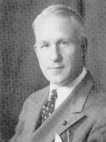 Frank H. McIntosh began his career with ten years at
Bell Telephone Laboratories in Murray Hill, New Jersey. He then became a
broadcast sales representative for the Graybar Corporation on the West Coast.
During WWII he was head of the radio and radar division of the War Productions
Board.
Frank H. McIntosh began his career with ten years at
Bell Telephone Laboratories in Murray Hill, New Jersey. He then became a
broadcast sales representative for the Graybar Corporation on the West Coast.
During WWII he was head of the radio and radar division of the War Productions
Board.
Early in 1942 Mr. McIntosh had a small consulting business in the Washington DC area designing radio stations and sound systems. He was affiliated with a Muzak franchise, Dr. Frank Stanton, President of CBS and Leonard Reinsch, Radio Advisor for Harry Truman. His business required high power, low distortion audio amplifiers, but none of those available could meet his requirements. In fact, most amplifiers failed to meet their published specifications. Being a perfectionist by nature he had an idea to develop a new amplifier which would have outstanding performance characteristics, high power and when measured, would meet all of the advertising claims. In 1946 Gordon Gow was hired as an engineering assistant to help develop his idea. The necessary materials to build the Unity Coupled transformer were just becoming available at that time. By 1948, the component parts of the Unity Coupled circuit were assembled into a symmetrically driven balanced output stage. Applications were filed for five basic patents. The first one was granted in 1949.
 The amplifier was called the McIntosh 50W1 Amplifier.
Although amplifiers like those designed in 1936 by Jefferson
Electric could produce 60 watts of output power from a pair of 6L6 tubes,
the 50 watt McIntosh amplifier enhanced performance with a wider bandwidth of
20 Hz to 20,000Hz and a lower distortion of less than 1%. An article was
published in the December 1949 issue of Audio magazine (then called Audio
Engineering) by Frank H. McIntosh and Gordon J. Gow titled "Description
and analysis of a New 50-Watt Amplifier Circuit". The Unity Coupled
transformer was shown on the cover.
The amplifier was called the McIntosh 50W1 Amplifier.
Although amplifiers like those designed in 1936 by Jefferson
Electric could produce 60 watts of output power from a pair of 6L6 tubes,
the 50 watt McIntosh amplifier enhanced performance with a wider bandwidth of
20 Hz to 20,000Hz and a lower distortion of less than 1%. An article was
published in the December 1949 issue of Audio magazine (then called Audio
Engineering) by Frank H. McIntosh and Gordon J. Gow titled "Description
and analysis of a New 50-Watt Amplifier Circuit". The Unity Coupled
transformer was shown on the cover.
However, the name “Unity Coupling” was not created until mid 1954. A contest to name the unique circuit was advertised in the January-February 1954 issue of High Fidelity magazine. So far, I have not been able to learn the names of the winners.
![]()
In a normal output circuit, using 6L6's in push-pull, the tube load impedance is 4000 ohms. A transformer is needed to match the typical speaker impedance of 8 ohms. This represents an impedance ratio of 500 to 1. The necessary transformer turns ratio is the square root of 500, or 22 to 1. Leakage inductance and shunt capacitance cause high frequency rolloff. It also causes notch distortion in class B operation.
The Unity Coupled transformer distributes the load to the output tubes and effectively reduces the impedance to 1000 ohms. The impedance ratio is lowered to 125 to 1. The turns ratio is reduced to the square root of 125, or 11 to 1. Leakage inductance and shunt capacitance are greatly reduced. By using the bifilar winding technique, leakage inductance is eliminated between primary sections.
The Unity Coupled circuit and transformer reduced distortion compared to conventional amplifier performance at that time. The transformers were made exclusively by McIntosh.
![]()
A Different McIntosh
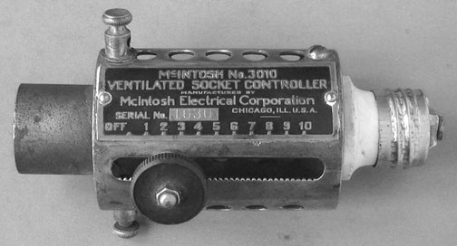
A McIntosh controller? Yes, but there is no relation to McIntosh Laboratory. This socket controller was made by McIntosh Electrical Corporation in Chicago, Ill. The company was in business long before McIntosh Lab. This particular product was an early lamp dimmer. It fitted into a standard electrical lamp socket and the lamp fitted into a socket at the left side. The brightness of the lamp could be varied by turning the black knob which moved up and down the track. Inside, a contact slid up or down on a resistor that was in series with the lamp. Of course, diverting some of the power to the resistor to dim the lamp caused the resistor to dissipate heat. Many holes were in the main body to ventilate the heat. A ground terminal can be seen at the top of the picture.
This company made many different electrical devices, many of which can be considered as “quack” doctor devices. Some were very complex. One such device was the McIntosh Modernistic Sinustat, a machine designed to treat sinus problems with small electric jolts. Another device is the Portable Wall Plate. This was claimed to provide electrical pulses to muscle tissue causing them to contract and consequently exercise them. This was adapted to treating paralyzed patients.
In 1922, McIntosh Electrical Corporation was split off from McIntosh Battery and Optical Corp which was in operation in 1907 or earlier. The McIntosh Electrical Belt was advertised in 1890 by its designer Dr. L. D. McIntosh.
![]()
1944
Maurice Painchaud joins the McIntosh consulting firm
 Frank McIntosh initially hired Maurice (Morris) as a
draftsman for his consulting firm in Washington. Morris gradually gained
responsibility for the entire manufacturing operation including finance,
purchasing, production and quality control. He graduated from Strayer College
with a B.S. degree in accounting and started his career with the U.S.
Government. Since joining McIntosh, he served as Controller and Chief
Administrative officer in the 50's, Vice President in the mid 60's and
executive vice president in the late 70's. He became President in June, 1989
after Gordon Gow passed away. Morris retired in May 1992. He was well liked by
everyone and was easy to talk with.
Frank McIntosh initially hired Maurice (Morris) as a
draftsman for his consulting firm in Washington. Morris gradually gained
responsibility for the entire manufacturing operation including finance,
purchasing, production and quality control. He graduated from Strayer College
with a B.S. degree in accounting and started his career with the U.S.
Government. Since joining McIntosh, he served as Controller and Chief
Administrative officer in the 50's, Vice President in the mid 60's and
executive vice president in the late 70's. He became President in June, 1989
after Gordon Gow passed away. Morris retired in May 1992. He was well liked by
everyone and was easy to talk with.
1947
The first company was formed and the name was changed from the consulting service of McIntosh and Ingles (Engles) to McIntosh Scientific Laboratory.
1949
In January the company was
incorporated and the name was changed to McIntosh Engineering Laboratory. It
moved from 1213 Wyatt Building, Washington 5, D. C. to 910 King Street in
Silver Spring, Maryland.
1950
Gordon
Gow becomes executive vice president of McIntosh.
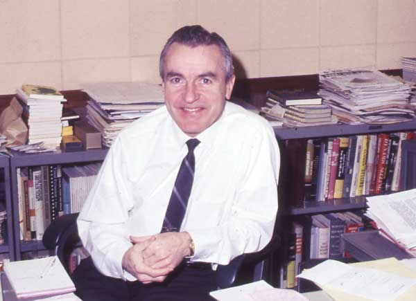
Gordon
Gow
picture from 1969
Gordon Gow was born in Lethbridge, Alberta, Canada. He started his career on the broadcast staff at a radio station in Calgary, but soon joined the Royal Canadian Air Force where he earned the rank of flight lieutenant. He served in Canada, England, West Africa and Gibraltar. The British Crown awarded him the distinguished "Member of the British Empire" award for radar related inventions.
After his foreign tour of duty was completed, Gordon was assigned to the British delegation in Washington, D.C. to explore common communication techniques, a need, which became apparent because of the various languages spoken by the allies during the war. In Washington, he met Frank McIntosh and joined with him to do research and development for a new amplifier.
The first preamplifier, the AE-2 was added this year.
Bill Scrivner was in charge of purchasing.
1951
In April, McIntosh Engineering Labs,
Inc. moved from 910 King Street in Silver Spring, Maryland to 320 Water Street
in downtown Binghamton, New York. The name was changed to McIntosh Laboratory,
Inc. Sidney A. Corderman joined McIntosh and was placed in charge of
engineering, research and development.
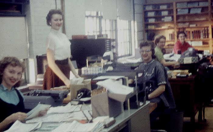
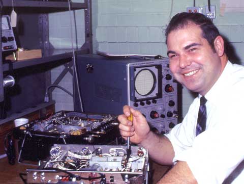
This is the office at 320 Water Street. The original picture was not very sharp.
McIntosh was on the second floor of the old downtown building.
Some people wondered if the old floor could support the heavy equipment.
The focus is bad but it looks like the assembly of a section of a 50W-2 amplifier.
1952
In the 1950's, McIntosh amplifiers and
preamplifiers were listed in electronics catalogs, such as Allied Radio in
Chicago, IL and Fort Orange Radio in Albany, NY. They could be ordered through
the mail.
In Canada, McCurdey Radio Industries, Ltd., 72 Front Street, Toronto, Canada manufactured McIntosh equipment under license. This included the MC-30 and MC-60 power amplifiers as well as the C-8 Audio Compensator.
 McIntosh exhibited at the 1952 Audio Fair. This small
picture was in the December 1952 Audio Engineering magazine. The amplifier,
probably a 50W-2, was sitting on top of the F100 speaker.
McIntosh exhibited at the 1952 Audio Fair. This small
picture was in the December 1952 Audio Engineering magazine. The amplifier,
probably a 50W-2, was sitting on top of the F100 speaker.
"Something new was added to this year's showing of McIntosh Engineering Laboratary. In addition to the world-renowned McIntosh amplifier there was displayed for the first time the new McIntosh speaker.. A corner enclosure, the new McIntosh development may well be expected to diversify the leadership which is maintained by the name McIntosh in the audio industry."
1953
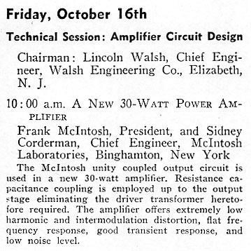
At the
fifth Annual convention of the Audio Engineering Society,
Sidney Corderman read the paper describing the new McIntosh 30-watt amplifier.
1954
McIntosh
records were available for a short time. Mr. McIntosh made many recordings in the Washinton DC area. I even bought one
after attending one of the Hi-Fi shows at the Hotel New Yorker. It was called
“Through the Sound Barrier with McIntosh.”
National Claims Unity Coupling
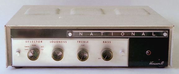
In 1954 the National Company in Malden MA, makers of ham radio equipment, entered the hi-fi market with the Horizon 10 and Horizon 20 amplifiers plus the Criterion AM-FM Binaural tuner and a horn loudspeaker system. The power amplifiers were advertised as having a revolutionary new output circuit employing "Unity Coupling." National literature claimed this feature was exclusive. "With unity coupling in the Horizon 20 and Horizon 10 amplifiers, the output transformer is no longer required to supply coupling between output tubes for distortion cancellation as in normal push-pull circuits. Instead, the transformer supplies only the impedance matching between the tubes and the load, thereby eliminating transformer caused impulse distortion."
This was in no way similar to the patented McIntosh Laboratory Unity Coupled circuit and transformer. Gordon Gow decided not to pursue the legal aspect of National's using the unity coupling terminology. The circuitry for the National amplifiers appeared to be poorly designed and constituted no threat to McIntosh. As it turned out, the line of National audio products lasted only a couple of years and were discontinued. The amplifiers reportedly were plagued with problems.
In the March 1953 issue of Audio
Engineering, the Industry People section reported the following:
"Entire audio fraternity well entertained and enlightened at February
meeting of AES in New York—featuring many of the most prominent personalities
in the audio field in a round-table discussion—on the platform were Wilfred B
Whalley, moderator, C. J. LeBel, Frank H. McIntosh, Jerry B. Minter, H. A.
Pearson, Herman H. Scott and Liewellyn Bates Keim."
1955
|
|
|
|
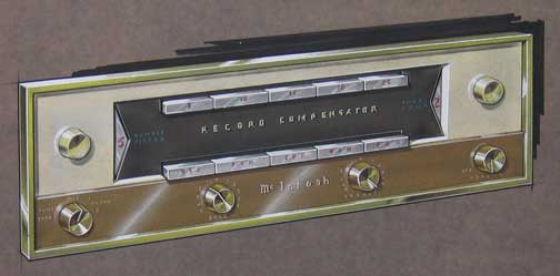
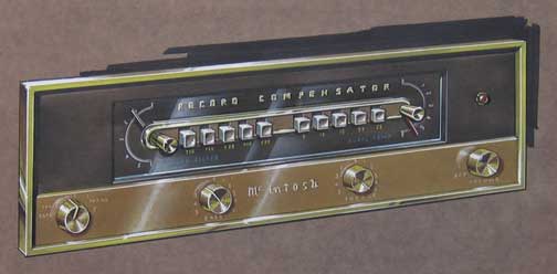
Here are renderings of a proposed new appearance for the McIntosh record compensator. They were submitted by George H. Kress Associates. The designs were not used and the reasons are not known. However, the design was reminiscent of the appearance of the MR55 tuner that went into production in 1957
In the August 1955 issue of Radio-Electronics an article was written by Robert F. Scott, Technical Editor, describing the circuit features of high-fidelity power amplifiers and in particular, the McIntosh MC-30 power amplifier. In the December 1955 issue, Sidney Corderman, Chief Engineer, McIntosh Laboratory replied in a letter to clarify the class of operation for the MC-30 amplifier.
McINTOSH MC-30 AMPLIFIER
Dear Editor:
I wish to extend sincere thanks from McIntosh laboratory for the excellent
article (August) covering our MC-30 amplifier.
There are several technical comments I wish to offer. Let me say, however, that
these comments are not intended to in any way depreciate the article. To the
best of my knowledge it is 100% correct.
Regarding the 1614's in the output stage, they do approach class-B operation.
However they do not operate into grid current as one might expect, except on
peaks when the amplifier is operated above the rated 30-watt level. The 12AX7
cathode follower is used to not only handle these peaks, but primarily to
provide a relatively low d.c. impedance to ground for the 1614 control grids.
This low impedance is necessary to prevent a change in bias for the 1614 tubes
due to reverse grid current. Such a bias change can cause excessive plate and
screen dissipation in the output tubes.
Regarding the 12BH7 load resistor connection, the a.c. load impedance presented
to the plates of the 12BH7 is greatly increased above the 12,000-ohm value of
the resistors used, as you mentioned. This impedance is four times that, or
48,000 ohms.
Sidney Corderman, Chief Engineer,
McIntosh laboratory, Inc.
Binghamton, N.Y.
1956
Construction began on the new building located at 2 Chambers Street just off Conklin Road where they are still located today.
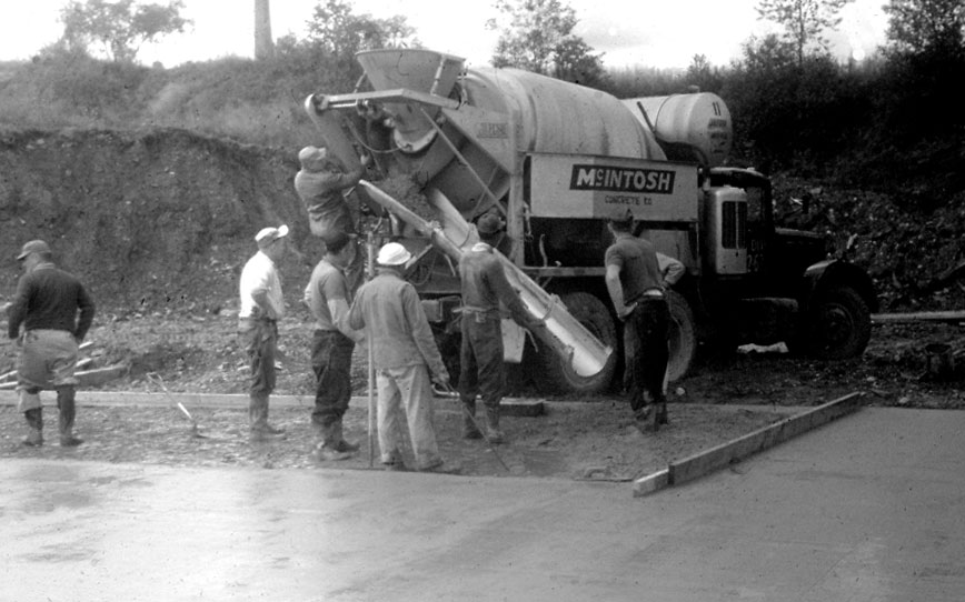
Oddly enough there was another McIntosh in Binghamton. This was the McIntosh Concrete Company and there was no connection with the lab except they were the ones to supply concrete. Here they are pouring the floor at Chambers Street.
1957
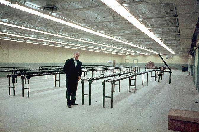
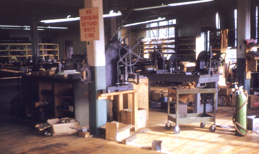
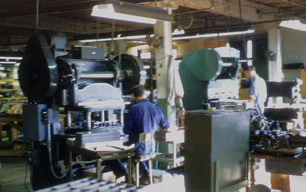
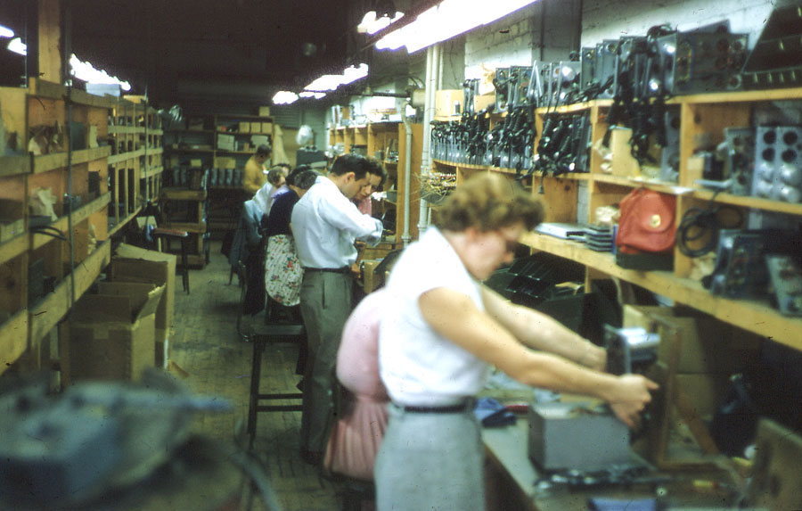
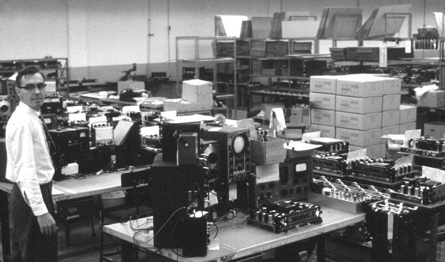
Here
is a picture of the new production area looking towards the front of the
building.
It was an exciting time for such an expansion. This area changed a lot over the
years.

Later, the hill leading to the apartments behind the lab and to the right side was graded. An addition to the rear of the lab was also made later. After grading, the side of the hill remained the same as it is today.
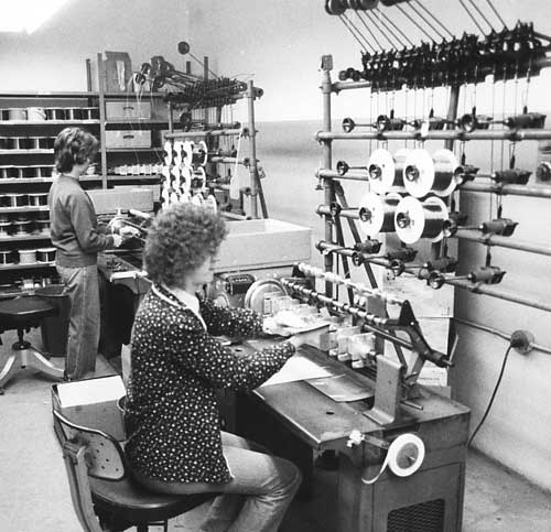
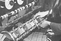 Some of the oldest and busiest machines at McIntosh
were the transformer winding machines. They run practically every working day,
year after year. The windings were made on a coil form or bobbin. Several
transformers were wound at the same time. Also, bifilar windings were made
using two separate reels of wire that were wound at the same time in the same
direction for each transformer.
Some of the oldest and busiest machines at McIntosh
were the transformer winding machines. They run practically every working day,
year after year. The windings were made on a coil form or bobbin. Several
transformers were wound at the same time. Also, bifilar windings were made
using two separate reels of wire that were wound at the same time in the same
direction for each transformer.
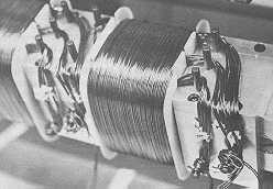 After the windings were completed, the cores were
added. The transformers were then inserted into a steel can and filled with a
tar potting material.
After the windings were completed, the cores were
added. The transformers were then inserted into a steel can and filled with a
tar potting material.
Later, when speaker crossovers were made at McIntosh, these machines were used to wind the crossover coils.
The first McIntosh tuner, the MR55, was introduced. Lawrence Arguimbeau designed the FM section and Bill Weeden the AM section.
1959
This year McIntosh introduced the C20 preamplifier. A black & white photo does not do justice to the red illuminated dial pointers. I first saw the C20 when I was working at the United States Army Signal Research and Development Laboratory at Ft. Monmouth, New jersey. This preamp was used in a demonstration of a sound system to simulate sounds of tanks. A system was also developed to project sound from a helicopter a mile above the ground out of the range of small arms fire.
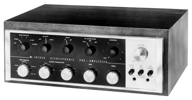
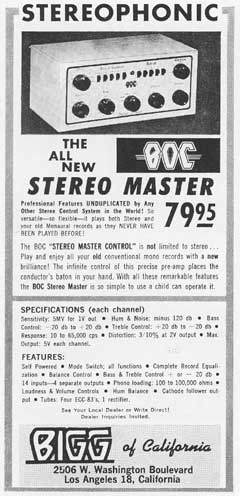 In the April 1959 issue of High Fidelity magazine, the
Bigg BOC Stereo Master preamp was advertised. It was made by Bigg of
California, 2506 W. W. Washington Boulevard, Los Angeles 18, California. It
looked very much like the McIntosh C8 series of preamplifiers. There were no
patents on the C8 and therefore no basis of legal action. Although this preamp
came out before I worked at McIntosh, I think that Gordon Gow treated this
situation the same as National using the "Unity Coupled" amplifier
claim. Simply that it was no threat. The Bigg preamp was very short lived.
Today, almost no one has ever heard of it. Interestingly, a two page ad
advertises the McIntosh C20 stereo preamplifier in the same issue of High
Fidelity.
In the April 1959 issue of High Fidelity magazine, the
Bigg BOC Stereo Master preamp was advertised. It was made by Bigg of
California, 2506 W. W. Washington Boulevard, Los Angeles 18, California. It
looked very much like the McIntosh C8 series of preamplifiers. There were no
patents on the C8 and therefore no basis of legal action. Although this preamp
came out before I worked at McIntosh, I think that Gordon Gow treated this
situation the same as National using the "Unity Coupled" amplifier
claim. Simply that it was no threat. The Bigg preamp was very short lived.
Today, almost no one has ever heard of it. Interestingly, a two page ad
advertises the McIntosh C20 stereo preamplifier in the same issue of High
Fidelity.
Another preamp that also appeared was the George Gott GDP50 preamp. It also looked very much like the C8 preamplifier.
1960
McIntosh sold the one and only kit
called the MK-30. It was identical to the MC-30. Sales were very low and it was
discontinued in 1961.
![]()
1961
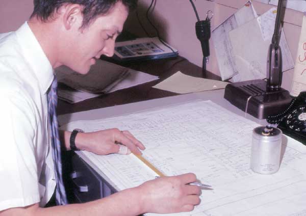
Dick Walter was in charge of production
This view is looking toward the rear of the building. The leaning objects at the rear are groups of folded packing cartons
1962
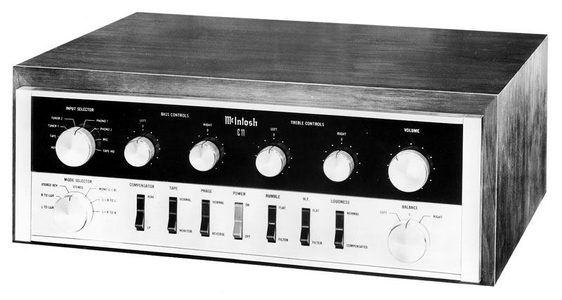
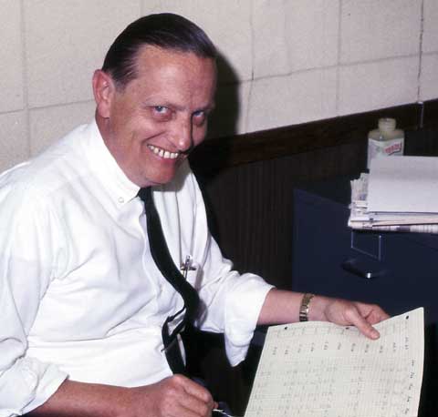
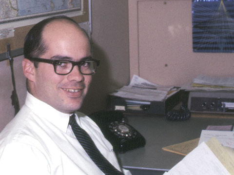
The C11 preamp was introduced this year.
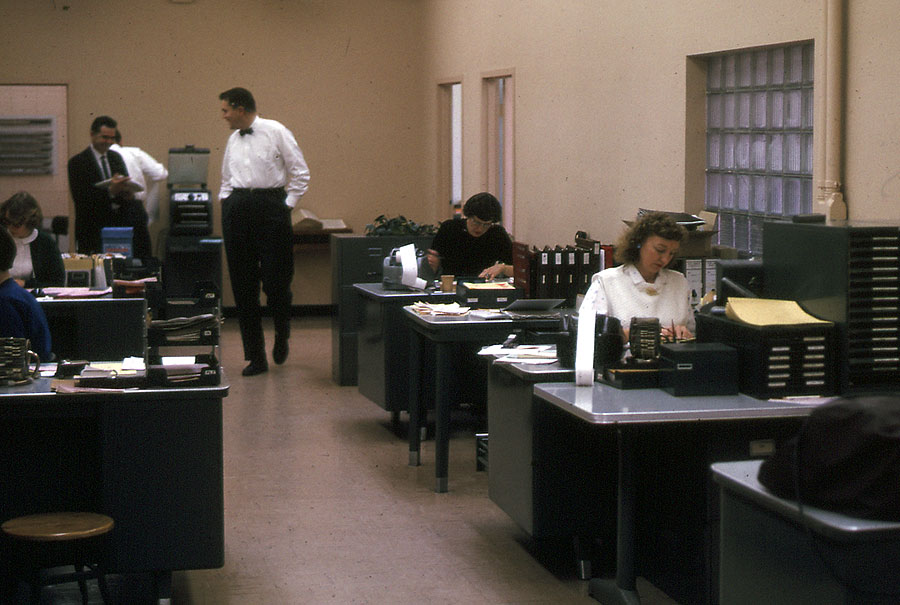
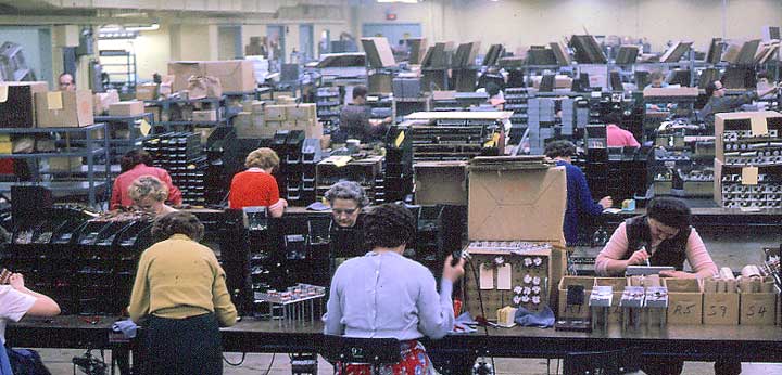
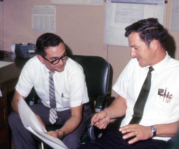
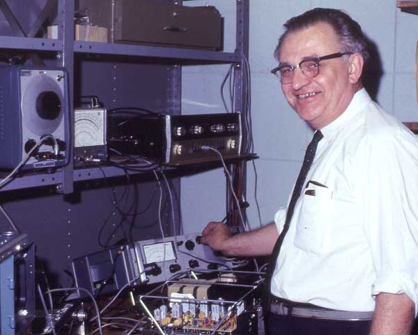
January 1962. The front office was all open. Later, it was divided into compartments. The glass blocks in the wall transmit light from the front entrance. Yes, that is Sidney Corderman with the white shirt and bow tie. Note the large open dictionary behind Sidney. Gordon Gow kept this right outside of his office. As I recall, the two pipes on the wall at the right were part of a vacuum system used to send paperwork for orders to the shipping department at the rear of the building..
Dave O'Brien was hired to head the McIntosh clinics.
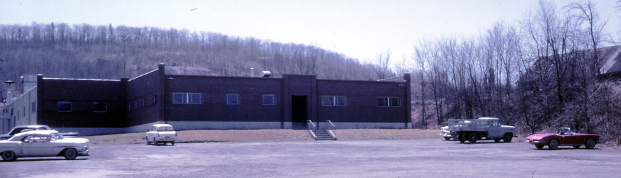
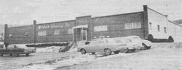
Dave O’Brien took this picture in April of 1962. Note that the McIntosh Laboratory Inc sign had not yet been added. In addition, the left section of the front was yet to be added as well as the shrubs around the front. The front entrance was changed later. Dave’s red Corvette is parked at the right.
The first tuner-preamp, the MX-110, was made in 1962 and was the first unit to use the McIntosh Panloc mounting system.
California Representative Show
From the December 1962 issue of Audio Times.
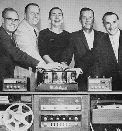
“A turnout of 1,800 encouraged the two reps, Frank Koessler and Mike Ross, who sponsored a special three-day Fall showing of audio lines at the Sportsman’s Lodge, Studio City, Calif. Not a séance, despite the laying on of hands, but expression of satisfaction by George Wells of Cliff Swanson Co., Dick and Mrs. Emmons of Emmons Audio, Frank Koessler of Koessler sales and Bud Wilson of Emmons, for successful San Fernando show.”
The hands-on amplifier, if you can’t see the name and model, is a McIntosh MC275 amplifier. How were we to know, 43 years later, that this amplifier would be so highly prized and sought after? Not only that, but several reissues have been made of what has become the McIntosh classic amplifier of all time.
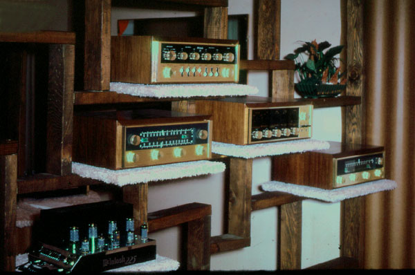
Typical
equipment display in a dealer store.
C11 preamplifier, MR66 tuner, C20 preamplifier, MC225 power amplifier and MR65
tuner
![]()
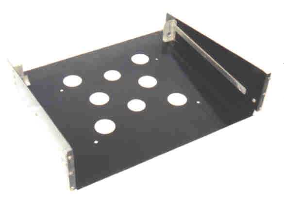 The first system was called Pan-loc, invented by Tom
Rogers at McIntosh. It was very similar to a fixed open rack shelf that was
used in standard relay racks but with the addition of a locking device on
either side. The sides and bottom were all one piece. The bottom is referred to
as a "pan". Later, the name was changed to Panloc, and the
"pan" was removed, leaving only the side brackets. The brackets could
be securely mounted on either side of the cutout in the equipment cabinet. A
clear plastic template was supplied to locate the cutout and the screw holes
for the brackets. After mounting the brackets, the unit could easily slide in
place. Two panloc buttons were located at the bottom left and right of the
unit. Pushing them in once locked the unit in place. Pushing them in once again
unlocked it. After unlocking, the unit could be pulled out for a few inches and
then it locked in position. Some units have controls on the top that could be
accessed at this position. The unit could then be released by pushing in on the
spring strips on both sides and pushing it back in place, or pulling it out to
remove it. The panloc system was discontinued in 1992.
The first system was called Pan-loc, invented by Tom
Rogers at McIntosh. It was very similar to a fixed open rack shelf that was
used in standard relay racks but with the addition of a locking device on
either side. The sides and bottom were all one piece. The bottom is referred to
as a "pan". Later, the name was changed to Panloc, and the
"pan" was removed, leaving only the side brackets. The brackets could
be securely mounted on either side of the cutout in the equipment cabinet. A
clear plastic template was supplied to locate the cutout and the screw holes
for the brackets. After mounting the brackets, the unit could easily slide in
place. Two panloc buttons were located at the bottom left and right of the
unit. Pushing them in once locked the unit in place. Pushing them in once again
unlocked it. After unlocking, the unit could be pulled out for a few inches and
then it locked in position. Some units have controls on the top that could be
accessed at this position. The unit could then be released by pushing in on the
spring strips on both sides and pushing it back in place, or pulling it out to
remove it. The panloc system was discontinued in 1992.
![]()
FM Mulitpath Indicator/Antenna Rotator
About 1962, I remember attending the New York Audio Fair and seeing a new McIntosh accessory. It was called the FM Mulitpath Indicator/Antenna Rotator, also referred to as the MI-1. It never went into production.
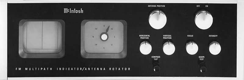
The left side had a oscilloscope display that showed FM multipath. The middle display had a compass pointer that indicated where the antenna was pointing. It included N, NE, E, SE, S, SW, W and NW. The compass indicator was used in conjunction with an antenna rotator. The two large knobs near the top were for antenna position (left) and power on and off. The row of smaller knobs was for Horizontal Position, Vertical position, Focus and Intensity. Two black knobs near the bottom right were for Compass Test and Scope test.
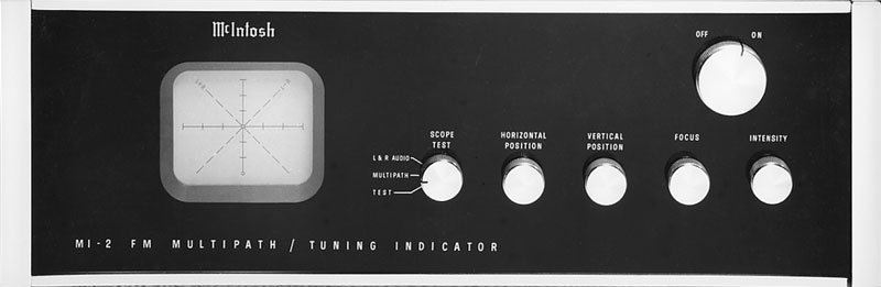
A suitable rotator mechanism was never found for this unit and the MI-2 FM Multipath/Tuning Indicator was produced instead.
![]()
Sidney Corderman’s brother, Warren, had been working in the sales department. Later, he decided to leave and work for the State University of New York (SUNY Binghamton). It was called Harper College at that time but is now known as Binghamton University.
![]()
1962
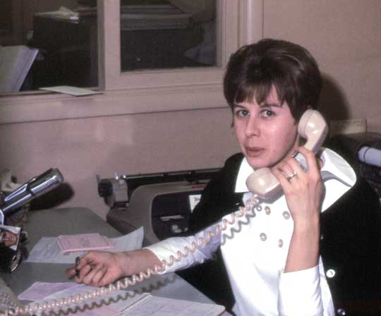
Fran started work at McIntosh at the end of 1962. She started out as the telephone operator and receptionist. As time went on, she was also making airline reservations and hotel bookings for Gordon Gow and Dirk Roos. After Warren left, she started working in the sales department, taking orders and managing inventory. When the ML-1C was in production, I remember calling her every day from Plant 5 with a list of serial numbers for more systems that were ready to be shipped. She was very pleasant to work with. Fran stayed there for 33 years and retired in 1995.
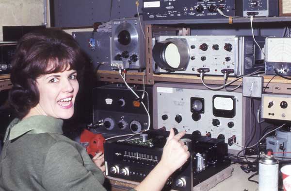
Sharon
worked for Al Hyle in customer service. She is working on an MAC1700.
Customer service was located in the main building next to the stockroom.
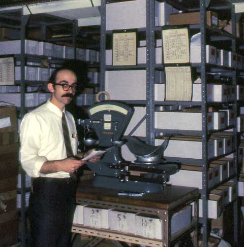
Mike
Spencer was in charge of the stockroom. He had hundreds and hundreds of parts
to keep track of.
The stockroom was located at the back of the main building.
1963
The C-22 preamp, MR-67 and MR-71
tuners were manufactured. They were the first preamp and tuners to use the
panloc system. The MA230 was also manufactured this year. It was the first
preamp/amplifier combination. The MI-2 was introduced as well. It was the first
unit to have an all glass front panel. All previous units, including the C20,
C-22, MR-67 and MR-71, had glass only in a portion of the panel.
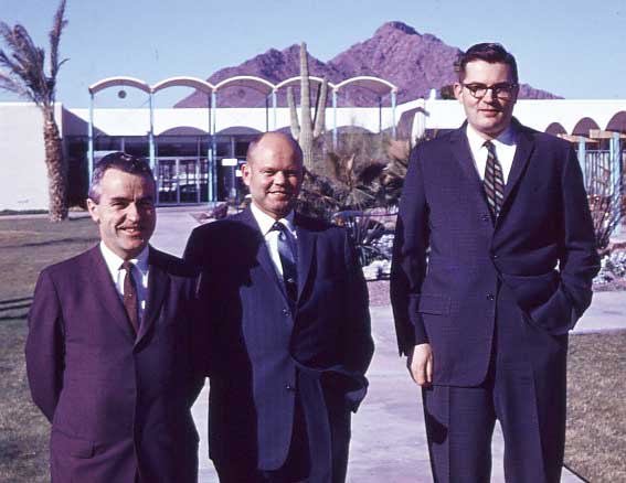
This picture appears to have been taken in Phoenix, Arizona. Gordon Gow (left) and Sidney Corderman (right). It might be Cliff Hendrickson in the center.
1964
The C24 preamplifier was manufactured
this year. It was the first solid state electronics that McIntosh produced. The
MI-3 was also produced this year. The MI-3 was the first performance indicator
to use panloc.
1965
The first receiver, the MAC1500, went
into production.
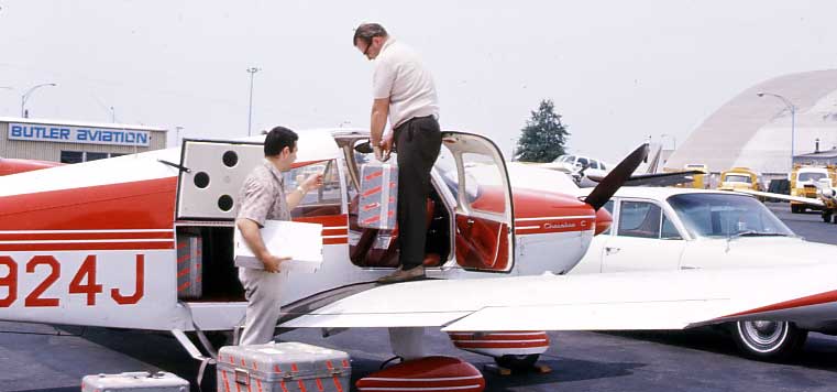
Gordon Gow often used chartered planes to visit dealers and customers who were having McIntosh equipment problems. Butler Aviation was located next to the Broome County air terminal. The name Butler Aviation was later changed to Broome County Aviation. This picture shows a single-engine Piper Cherokee. I flew on the chartered flights several years later but on twin-engine Piper Navajo planes.
1966
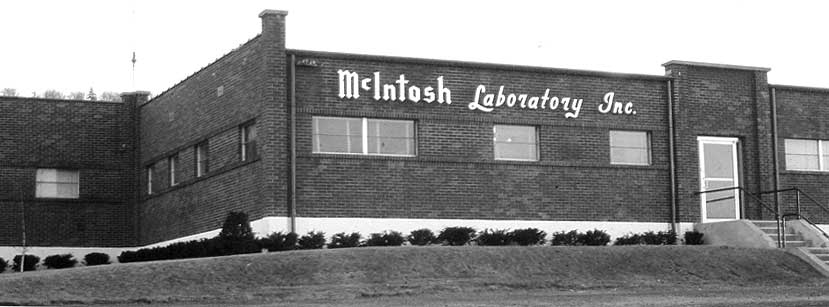
This is the way the left side of the main plant looked in early 1966. The McIntosh sign and front entrance had been added by then. In 1967, a new section was added to square off the front of the building. It was to be used for the engineers plus a reverberant room and a listening room for loudspeaker research and development.
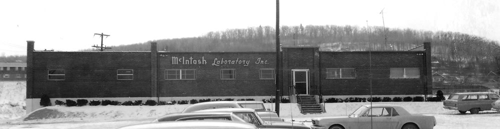
This was the way McIntosh looked when I came for an interview with Sidney Corderman on a cold day in February, 1967. There were snowflakes in the air. It was typical weather for Binghamton at that time of year. Back then, there was no canopy over the front entrance at all and the shrubs at the base of the foundation were very small. I was a little dismayed to see that part of one of the elements on the FM antenna on the roof was missing.
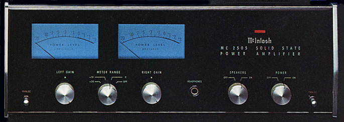
I remember seeing their production line for the first time. The new MC2505 power amplifier was being assembled and I thought it was the most beautiful amplifier I had ever seen, with a gorgeous illuminated, black glass panel and blue meters. I had never seen anything like it before. It was love at first sight and I couldn’t help wanting to have one!
That evening, Sidney and his wife, Sara Jo, took me to dinner at the Scotch & Sirloin restaurant in the Vestal Plaza. This was an excellent and popular eating place. Little did I know I would be hired and buy a house not more than three blocks away from the plaza and that I would own much of the distant wooded hill behind the lab.
I began work in March to design loudspeakers but first I designed The C26 Stereo Preamplifier that was needed to replace the C24 preamp. I also designed the audio section of the MX112 tuner-preamp using C26 circuitry. The audio features were simplified, but the circuit boards were the same. I later designed the MQ101 Environmental Equalizer using a portion of these circuits.
The MAC1700 receiver was also produced this year. This was a hybrid unit. The preamp and amplifier sections were solid state, but the tuner section was tubes.
![]()
The New MC2505 Amplifier
The MC2505 was the first separate solid state power amplifier made by McIntosh. This amplifier was a major step in McIntosh amplifier history and introduced many features still used in McIntosh amplifiers today. It was the first amplifier to have an all-glass front panel, panloc mounting, illuminated, peak-reading output level meters, Sentry Monitor circuitry and autoformers. The MC2505 autoformers were a new concept in the history of McIntosh transformer design.
Transistor power output circuits can match 8-ohm loads directly. This eliminates the need for the output transformer for most manufacturers. However, output stages that are designed to operate into an optimum load of 8 ohms can double or quadruple heat dissipation when operating into 4 or 2 ohm loads. At some frequencies, speakers rated at 8 ohms can dip as low as 4 ohms. Some 4-ohm systems can dip even lower. This mismatch can cause the amplifier to exceed its thermal dissipation limits.
On the other hand, if an amplifier is designed for an optimum load of one or two ohms, a low impedance load would be no problem. However, less power would be available for a speaker having 4 or 8 ohms impedance.
The unique McIntosh output autoformer was the answer. Since McIntosh output stages were connected in a single ended push-pull circuit, one side of the output was always connected to ground. They were typically designed to work into an optimum load of 2.1 ohms. The matching autoformer was connected directly to the output. In the MC2505 amplifier, the matching output was for 4, 8 and 16 ohms. Other impedances became available in later amplifiers. Full continuous amplifier power could be delivered to each of these loads. There qas no danger of exceeding safe limits or overheating.
The autoformer also protected the speakers from damage in the event of amplifier failure. Should a direct current component appear at the amplifier output, it was shunted by the low DC resistance of the autoformer, instead of passing through the speaker voice coil, which could damage the speaker or even cause a fire.
McIntosh autoformers continued to be used in the "top-of-the-line" amplifiers. They were all designed and manufactured by McIntosh. Although the autoformers added extra cost, weight and took up extra space, they assured a safe, optimum match to a variety of speakers and speaker hook-ups. They were constructed and performed in the McIntosh tradition of excellence.
Although the autoformer provided an efficient match between the power transistor output and a variety of load impedances, a short circuit at the amplifier output or a load that was much lower than the selected autoformer tap could cause excessive current to flow in the output transistors. To complement the new transistor amplifiers, the McIntosh Sentry Monitor circuit was developed which prevented destructive current levels from occurring under any conditions. This circuit sensed the dynamic operating time, voltage and current of each amplifier output stage and controlled the current flow, confining it to non-destructive limits. The arrangement assured complete circuit reliability for all load conditions. The Sentry Monitor did not limit the rated power output available from the amplifier in any way. McIntosh power amplifiers continue to use the Sentry Monitor circuitry.
![]()
A primary concern of using meters to accurately show levels of music was the rise time. This involved not only the meter capabilities, but also the actual rise time of the musical instruments themselves. It brought up the fundamental question of whether a 20,000Hz square wave could exist and be propagated in air without being differentiated. Gordon Gow explained that although several experiments with a starting pistol showed varied results, the fastest rise time was found by striking two pins together. To exhibit rise times like this, the mass of an ordinary meter movement was too high to accurately show peaks. The MC2505 design provided driving circuitry that made the meter movement follow the fast rising waveforms to an accuracy of over 90%. By following the waveform, however, the meter movement could then be too fast for the eye to follow. Additional circuits made the peaks time-stretched, controlling the needle movement. Later, my research showed that further improvements were still needed for the meters.
When I started at the lab, I learned that Mr. McIntosh would write out a check for $100.00 right on the spot to any employee who would quit smoking from that time on. The agreement was that if they started smoking again, they would have to pay him $200.00. His plan worked very well. I don't know of any employee who started smoking again.
![]()
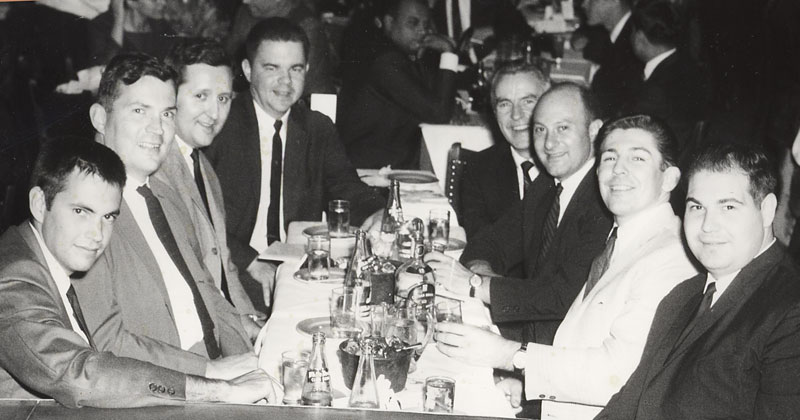
In 1967, a few of us were able to accept Gordon Gow’s invitation to go to the Latin Quarter in New York City for the evening. This included (left to right) A.P. Van Meter (an engineer who used to work at McIntosh), Sidney Corderman (Vice President of Engineering and my boss), Mila Nestorvic (engineer), me (engineer), Gordon Gow (Executive Vice President), Fred Shoninger (dealer), unknown, and Jim Grimm (engineer).
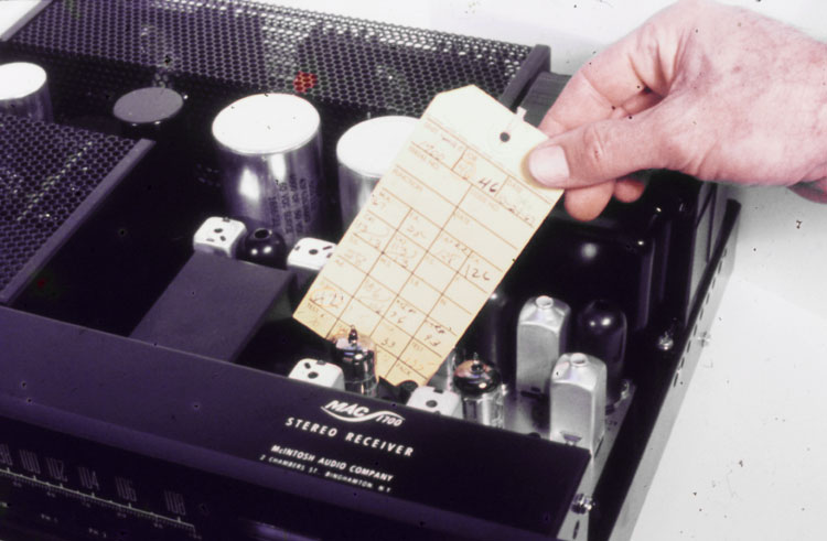
Also this year, the MAC1700 receiver went into production. Here it is shown with the completed inspection test card. Every piece of McIntosh equipment had one of these on the production line. The 1700 was the first receiver to have a solid state preamplifier and power amplifier. The tuner section was all tubes. I assembled one of these myself and it ran for years and years. I later gave it to my older son and it continued to run well. This was not unlike many pieces of McIntosh equipment that worked so well and so long that it was handed down from generation to generation.
![]()
1968-1969
Engineering at that time was in a relatively small area that was part of an addition to the left front corner of the main plant. Each of us had a narrow isle with a bench and shelves for test equipment and more shelves on the other side. There were only a few of us. Jean Filon was designing tuners, me designing the C26 and then speakers and Mila Nestorvic who designed amplifiers and a preamplifier. Jim Grimm had been hired to work on amplifiers and to replace Dave Campbell. Dave left after his wife, Toby, had been killed in a plane crash at La Guardia Airport along with Dick Bucci (McIntosh advertising) and his wife. Dick was the pilot of a small plane and a larger plane literally landed on top of them. I attended the services at the funeral parlor but it was closed casket and understandably so.
Ron Evans Joins McIntosh
 Soon after that, Ron Evans came for an interview with
Sidney Corderman. Sidney was recovering from the flu at that time and asked me
to help interviewing Ron. That evening, Ron and his wife, Sidney’s brother,
Warren, and his wife and my wife and I all went to the Scotch & Sirloin
restaurant. We all had an enjoyable time and I was impressed with Ron. He was a
knowledgeable, pleasant, down-to-earth person who I thought would fit in well
with our engineering group. He was with a company called TRW, as I recall, in
Chicago. Sidney also interviewed him at home.
Soon after that, Ron Evans came for an interview with
Sidney Corderman. Sidney was recovering from the flu at that time and asked me
to help interviewing Ron. That evening, Ron and his wife, Sidney’s brother,
Warren, and his wife and my wife and I all went to the Scotch & Sirloin
restaurant. We all had an enjoyable time and I was impressed with Ron. He was a
knowledgeable, pleasant, down-to-earth person who I thought would fit in well
with our engineering group. He was with a company called TRW, as I recall, in
Chicago. Sidney also interviewed him at home.
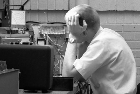
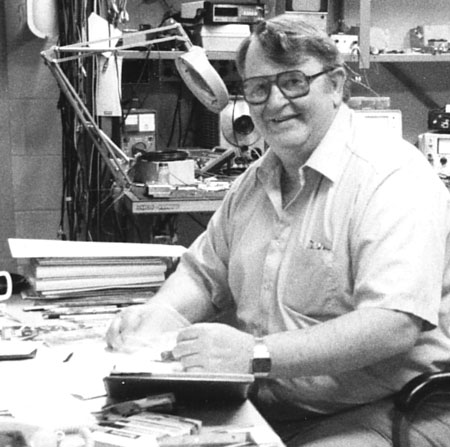
Sidney asked me for my recommendation and I gave him an all positive review. Ron accepted the job. Little did any of us know that Ron would eventually be in charge of engineering. I took this picture of Ron, who was busy solving a circuit problem at his bench back then but I didn’t tell him I took it until much later.
My C-26 went into production. It was the first preamplifier to have an all glass front panel. The C26 was sold until 1977. It was replaced with the C27 that was sold until 1982. The main differences were the cosmetics. The speaker switches, filter switches and power switch were relocated. The circuitry remained the same, but the phase switch and center channel level control were eliminated.
Here is Jim Grimm, a McIntosh engineer in 1969, working on a revised MAC1700 receiver. Jim adapted a triac circuit to protect the loudspeaker from DC current in case of output transistor failure. He was also the only person to notice that the meter switch on the MC2505 amplifier went from the off position to the most sensitive position before going to the other less sensitive positions. The switch was changed to the least sensitive position after the off position. Jim also developed the MC50 and MC100 amplifiers. I remember one day there was a big bang and a cloud of white smoke rising to the ceiling. Jim had installed one of the big filter capacitors in a power amplifier in reverse. The filter can went straight up and no one was hurt. We were all impressed.
Ken Nield worked in engineering. Here he is working on a layout for a power amplifier and there is one of those capacitors like the one that went up in smoke for Jim Grimm. Engineering solved all of the problems of mechanical dimensions It included panel illumination, printed circuit board layout, parts lists and many other things essential for production of new products.
Here is Richard Pensky and Ken discussing another one of those engineering problems.
![]()
1970
This picture was from the Binghamton Press, Tuesday, March 24, 1970. A short article concerned “McIntosh Laboratories, Inc. planning an eventual move from its headquarters plant at 2 Chambers Street in the city to a new facility, possibly at Broome Industrial Park in Kirkwood. The firm would consolidate its other two Broome operations into a new plant, to be built with state and federal government agency loan associations. The plant would cost $1,500,000. Frank H. McIntosh, president of McIntosh Laboratories, confirmed the plans, but said the company has yet to decide on a site. The new plant would cover 100,000 square feet and add about 125 jobs to the current 250-employee McIntosh payroll. The company had been growing at about 15% a year to the current sales of about $6,500,000 per year.”
It was later decided not to move at that time. Instead, in the summer, the acoustics lab was moved to a new facility in Hillcrest, a few miles north of Binghamton. This was known as plant 5. Plant 2 at Bevier Street and plant 3 at Barlow Road remained where they were as well. The actual expansion took place several years later in Conklin, but the main plant still remained at the same location.
The ML-1C speaker system went into production. The first systems were built by United Speaker Systems in East Orange, NJ. The systems were inspected and tested at McIntosh before shipment to dealers. They sold very well.
Bill Thompson was added to our engineering staff after I began work there. He was a very pleasant person and always had a laugh about something or other.
 \
\
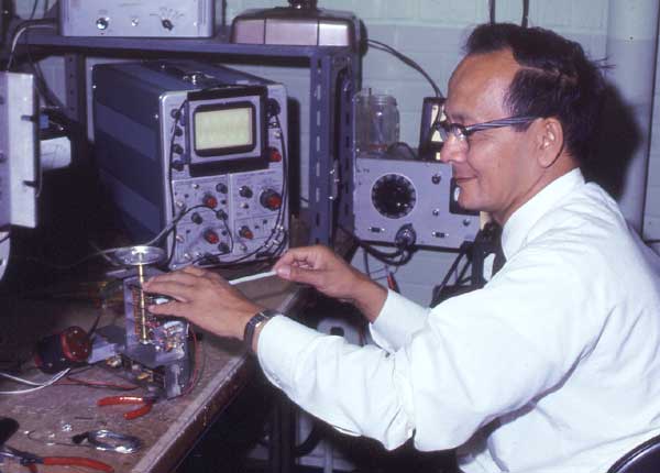
Here is Jean Filon working on design of a new tuner. Jean was the rf engineer and designed several tuners and tuner sections including the MX112, 113, 115. He was also involved with the MR71. He had realigned my MR71 tuner when I first came to McIntosh. Jean had been working at McIntosh before I started in 1967.
Dick Hickok was in charge of maintaining all of the test equipment both for the lab and production. All equipment had a regular maintenance schedule to ensure correct performance. Dick usually had an assistant to help with the work. Dick had started working there before I was hired.
![]()
1972
Larry Fish Joins McIntosh
Larry Fish joined McIntosh as Chief Electronics Engineer. Larry was very knowledgeable and pleasant to work with. Larry and I both reported to Sidney Corderman, who was vice president in charge of engineering. Larry graduated from Leominster High School and Taber Academy in Boston, MA. He also attended Massachusetts Marine Academy and Tufts University Extension in Denver, CO where he received his electrical engineering degree. He served with the U.S. Air force during the Korean war. He worked at H.H. Scott in Maynard, MA where he was chief electronics engineer, and met his future wife, Dot. From 1969-1972 Larry and his family lived in Japan where he worked as vice president of Teloem, Inc., a subsidiary of Tokyo Electron. He retired in 2003 as vice president of McIntosh. He was a volunteer fireman with the Chenango Bridge Fire Department and was also a pilot who enjoyed flying his own plane. Larry loved woodworking and building. In 1980 he built his own summer camp on Lake Maranacook in Readfield. He and his wife moved to Maine in 2004
Larry Fish, Jr, 74, formerly of Chenango Bridge, died Friday, February 9, 2007 in Lewiston, Maine. He was born in Fitchburg, MA , on April 7, 1932, the son of Lawrence and Selma (Nelson) Fish. He is predeceased by a son, Paul Zicus and a sister, Sally Wooster. He is survived by his wife of 42 years, Dorothy “Dot” Fish, Readfield, ME; two sons, Brad Fish and his wife, Sandy, Binghamton, NY and Lawrence W. Fish III, Chester Springs, PA; three daughters, Heidi Quinlivan and her husband, John, Honeoye Falls, NY, Kathy Verdone and her husband, Gary of Waterford, CT, Peggy DeMarco and her husband, Al, Leominster, MA; a brother Nelson Fish, Las Vegas, NV; several grandchildren, great-grandchildren, nieces, nephews and cousins.
![]()
A visit with Dr. Fletcher started a unique McIntosh research program.
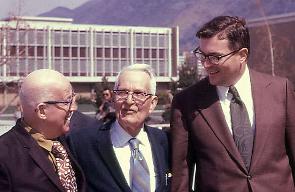
At the end of March, Sidney Corderman and I traveled to Brigham Young University in Provo, Utah to visit Dr. Harvey Fletcher and learn of some of the work that he had accomplished. We were particularly interested in the research he had done on music spectrum and peak levels. Many people remember Dr. Fletcher for the well-known Fletcher-Munson curves related to hearing and sound level.
In this picture that I took, left to right is Frank Young Gates, Dr. Fletcher and Sidney Corderman. Frank Gates used to be the McIntosh representative for the Rocky Mountain area including New Mexico, Utah, Colorado, Idaho and Montana. He was related to Brigham Young and lived in Salt Lake City. Frank had been called by the church to serve and had given up his job as a McIntosh representative. I took this picture of these three at the Brigham Young University Campus.
Dr. Fletcher was born in Provo on September 11, 1884. He graduated from Brigham Young University in 1907 and received his Ph.D. summa cum laude from the University of Chicago. In 1916, He joined Bell Laboratories and served as director of physical research until his retirement in 1949. While at Bell in 1933 he developed the first stereophonic sound system. The demonstration was conducted in the Hall of Music in Philadelphia. Leopold Stokowski agreed to participate with his orchestra. The music was transmitted over General Telephone lines to constitution Hall in Washington, D.C., where it was reproduced before a large audience of prominent national figures. It was called auditory perspective dimension sound, later to be known as stereophonic sound.
Fletcher was named professor of electrical engineering at Columbia University after his retirement from Bell Laboratories. In 1954 he became dean of the new College of Physical and Engineering Sciences at Brigham Young University and was later dean emeritus of the school.
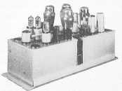
We learned of the work that had been done at Bell Labs on measuring the spectrum and peak acoustic output of musical instruments. An array of filters, tubes and relays were used to make the measurements. Sivian, Dunn and White presented a paper describing their work at the Acoustical Society of America in December of 1929. It is still valid today. Much work was also done on speech and speech recognition. Dr. Fletcher shows us the horn speakers used in the 1933 stereo demonstration.
The information we gained gave us a much better perspective on the demands placed on amplifiers and speakers to reproduce music and voice. It later led to our own research.
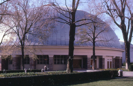
Frank Gates had driven us from Salt Lake City south to Provo. When we returned from our visit with Dr. Fletcher, Frank took us on a tour of the visitor center and Tabernacle of the Mormon Church. Visitors were not allowed in the main church across Temple Square. The picture below is the outside of the dome-shaped auditorium of the Tabernacle. It was completed in 1875 and is 150 feet wide, 250 feet long and 80 feet high. The acoustics are very unique.
I was very interested to see the tabernacle as I had been a fan for many years of the Sunday radio broadcasts from the Tabernacle. (Richard Condie and the everlasting hills). It was great sound for both organ and chorus and great for evaluating the sound of loudspeakers.
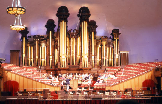
There was a group of visitors there when we entered and all of the lights were turned on that were used for the TV and radio broadcasts. There were many microphones located at many different places. At the left and right sides of the organ pipes in the back are two large speaker systems that were recently added. These were used to play back recordings for visitors. A paper was presented at the Audio Engineering Society about the design of these speakers for the Tabernacle by JBL.
Here is a picture seen from the choir section and the organ console in the center and the white chairs for the orchestra further back.
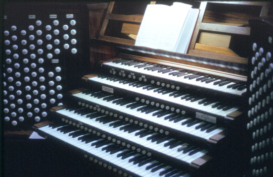
There are actually 11,623 pipes in all and 206 ranks of voices. The original pipes were made from wood. Originally powered by hand-pumped bellows and later by water power, the organ is now powered by electricity.
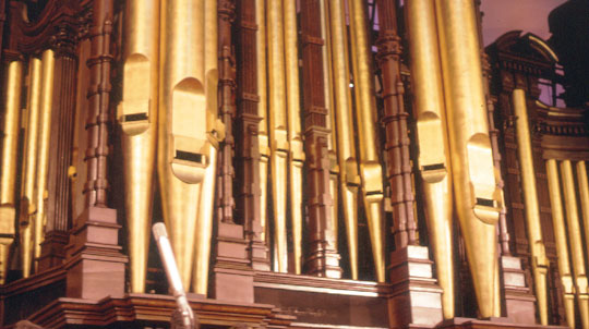
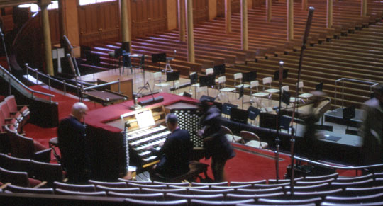
The most exciting part of the tour was when Sidney and I were allowed to go in back of the organ and see all of the original pipes that were played from the main console. I understood that the gold-colored pipes that are normally visible are only decorative. The organ was built by Joseph Harris Ridges from England.
![]()
New technology made instrumentation much less expensive and time-consuming compared to the work done by Dr. Fletcher many years ago. Gordon Gow decided it would be to our advantage to do some research of our own. I was responsible for measurement of the musical spectrum and peak levels. Some percussion instruments were rented and then finally purchased. Among these were a kettledrum, bass drum, snare drum, cymbals, Chinese gong, triangle, tambourine and wood block. I brought my violin; Wayne Paulson brought in his trombone; and Jeff Zwieben brought his dog in to bark—incredibly loud. This assembly reminded me of The Young Person’s Guide to the Orchestra by Benjamin Britten plus a dog.
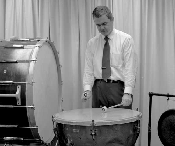
The Bruel & Kjaer 3347 real time analyzer had just been purchased and was ideal for use in this project. It was a 1/3 octave analyzer that had a peak hold feature. The analyzer came with six additional class III filters that extended the measuring range from 12.5Hz to 40kHz. In addition, I also used the Bruel & Kjaer sound level meter with a peak hold feature for broadband and octave band measurements. The peak level of the bass drum and cymbals in the listening room is almost 120dB. Lots of room gain there. I thought the level for the same instruments in the concert hall would be less than 105dB out in the audience. Later, I made more measurements were made at the Binghamton Symphony..
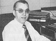
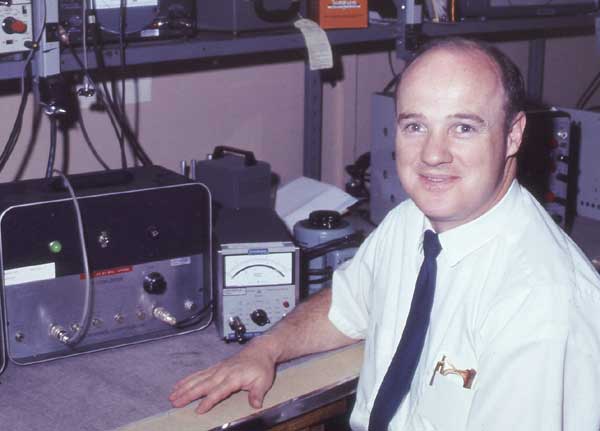
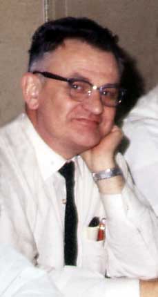 Bill Thompson also played the violin in the Binghamton
Symphony. Bill had previously been an engineer at Westinghouse and belonged to
the Catgut Society. That is an organization devoted to violin making and
research. In those days, concerts were played at the Binghamton West Junior
High School auditorium. Before the concert started, I would wait until Bill was
looking out in the audience and wave wildly at him. He would nod his head
modestly in acknowledgement. I think, since he was in front of many people in
the audience by that time, he was reluctant to wave and create a one-man
grandstand play. His picture is at the left.
Bill Thompson also played the violin in the Binghamton
Symphony. Bill had previously been an engineer at Westinghouse and belonged to
the Catgut Society. That is an organization devoted to violin making and
research. In those days, concerts were played at the Binghamton West Junior
High School auditorium. Before the concert started, I would wait until Bill was
looking out in the audience and wave wildly at him. He would nod his head
modestly in acknowledgement. I think, since he was in front of many people in
the audience by that time, he was reluctant to wave and create a one-man
grandstand play. His picture is at the left.
I also made measurements using the Bruel & kjaer sound level meter at many of the Binghamton Symphony concerts. This included wide band and octave band measurements. I usually sat in the first row of the balcony, but sometimes sat up front on the main floor. Not only was the musical analysis interesting, but also the audience applause. The initial applause after a performance was always the loudest. No matter how many times the conductor or guest performer returned to the stage, nothing was ever as loud as the first burst of applause.
Here are a few measurements that I made at one particular concert in November of 1971. All readings were made on the C scale of the sound level meter.
|
Voice announcement |
60-65dB |
The results of all these investigations were used in many different areas. Peak level measurements provided valuable information for electronics. I measured the peak output of a variety of phono cartridges. I connected the cartridge output directly to the input of the Bruel & Kjaer sound level meter in place of the microphone cartridge. A load of 47k and 65pF was used. The input impedance of the sound level meter was over 25 meg and the input capacity is accounted for. I select a wide range of music and records including Sheffield Labs direct-to-disc recordings. The peak hold feature of the sound level meter made it easy to read the highest voltage. These results were very useful to ensure conservative designs in the McIntosh preamplifier phono sections.
By connecting the Bruel & Kjaer microphone output directly to the McIntosh power amplifiers, I was able to show that the meter and the power guard light did not always agree for a live cymbal crash. As a result of my research, further improvements were made in the power amplifier meter circuitry.
My research not only enhanced McIntosh credibility and conservative product design, but also gave a handle on some real numbers for real instruments. It was also interesting to show that the spectrum content of program material, particularly at 16, 20, 25 and 31.5Hz was significantly lower than the upper bass energy. It showed why only a moderate increase in power was required for the deep bass when using the ML-1C and equalizer.
![]()
Visit to Arizona
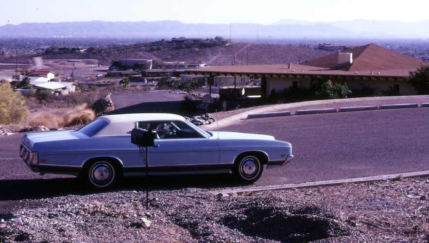
On our way back from Salt Lake City Sidney and I stopped in Phoenix. We knew that Mr. McIntosh had bought a mountain, really a hill, in the Phoenix area. We stopped by in a rented car to check it out. This view was at the main street entrance. It would be much better at the top of the hill.

One side of the hill had been bull-dozed and a paved road established to the top where his house would later be built. The leveled area can be seen near the top. The area is very dry and some small Sugaro cactus can be seen growing on the hillside.
My father and Sidney’s father both lived in Sun City that was a few miles north of Phoenix. By coincidence they were both ham radio operators as was Sidney. By further coincidence, Sidney’s mother and my mother had passed away on the same day in 1970. We stayed at my father’s house that night and returned home the next day. While at my father’s house, I remember seeing in the Arizona Republic newspaper an article titled something like “Eastern Industrialist Defaces Landscape.” It was probably because of the steep road that was created to get to the building site. Mr. McIntosh retired and moved into his house in 1977.
![]()
An article was published in the Binghamton Press on Thursday, Nov. 2, 1972. The headline is:
"Creating His Own Game preserve Is City Industrialist's Idea of Fun."
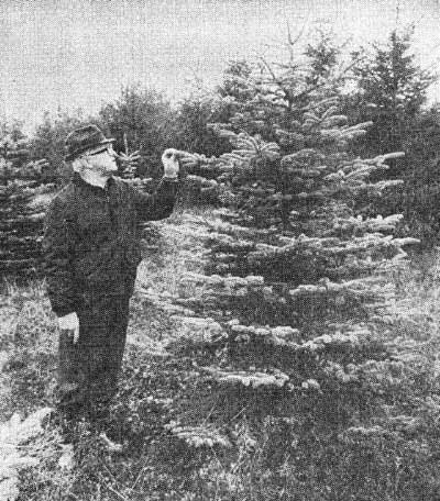
From Little Seedlings Grow
“Binghamton businessman Frank McIntosh looks over one of the thousands of pine trees he has planted over the last 10 years on his game preserve in northwestern Broome County. The 66 year-old industrialist's idea of a fun weekend is suited up in faded work clothes and hip boots, hopping on a tractor and pulling tree stumps and underbrush from the bed of a 25 acre swamp. 'I like to get our there to work and sweat up a storm and feel like I'm doing something useful.' says McIntosh, president of Binghamton's McIntosh laboratories, Inc., makers of high fidelity speakers, receivers and amplifiers.
In 1959, McIntosh began buying up farms in the towns of Maine, Naticoke and Barker, at first as an investment, and then for a pastime--to create a game preserve where animals could be admired and roam freely with out fear of hunters.
Today McIntosh owns 1,700 acres of rural property in northwestern Broome County, has planted more than 75,000 trees and is hard at work clearing dead brush and stubble in a swampy section where he plans to create a 25-acre lake.
Mcintosh estimates that by the time he finishes developing his unofficial game preserve, he will have invested as much as $200,000, including the purchase of 17 farms. In property taxes alone, he pays about $10,000 annually, he says.
Raised in Omaha, Neb., McIntosh spent summer vacations on a nearby farm. In 1938, he bought his first tract of property in dry southern New Mexico, where first he started planting trees and filling ponds for animals. Within two years he owned almost 8,000 acres of rustic land in New Mexico, Arizona and California."
![]()
At the main plant there was a bottled spring water dispenser just outside Sidney Corderman’s office. In the adjoining cabinet there were the makings for coffee and tea. The water could be dispensed cold or heated. One day, I came to visit Sidney and the carpet was wet even into his office. The heavy glass bottle had slipped away from someone who was changing to a full bottle and it broke. Sidney said there was a small tsunami in the direction of his office. Later, the bottles were made of plastic. Sometimes there would be a box of chocolates or some other goody on the cabinet next to the water dispenser. I think these were donated by persons who would rather share than gain all those calories.
Each Christmas, the loudspeaker engineering people were invited to an employees only Christmas party at noon time with the rest of the engineering department that was located in a different building. Each person was asked to bring some kind of food or beverage for the party. We had a great time sampling all of the different dishes. Behind the scenes, I think the wives did most of the work. Although my home-made chocolate chip cookies were popular, my wife’s coffee rings were the best.
![]()
|
About This Site |
||
|
|
More text and pictures about McIntosh will be added as my research continues. Any comments, corrections, or additions are welcome. |
|
|
|
All
contents are copyrighted |
|