Welcome to Roger Russell's Page
about the Ionophone
Loudspeaker.
A History
Copyright
1996-2004 by Roger Russell
All rights reserved
No portion of this site may be reproduced in whole or in part
without written permission of the author.
|
The information on this page has been gathered from my personal experience, magazine articles, and reviews of the Ionophone. Any additions, corrections or comments are welcome. I will be happy to post information for anyone who can supply replacement quartz elements, electrode elements or other parts or information about the Ionovac. |
|
Originally called the Ionophone, it was sold under the name of Ionovac
by the DuKane Corporation, St. Charles, IL, Electro-Voice, Buchanan, MI and
IonoFane by Fane Acoustics Ltd., Batley, |

That's on This Page?
|
|
![]()
General History and How It Works
 The idea of ionizing
air particles and moving them with the influence of an electric field dates
back to the late 1800's when Poulson demonstrated his singing arc. In 1900
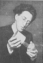
Duddell also demonstrated a singing arc. It was not until 1946, however, that a
French inventor by the name of Siegfried Klein (pictured at the right) thought
of confining the arc to a small quartz tube and coupling it to a horn. He
maintained that such an arc could be used for generation of subsonic or ultrasonic
waves as well as a microphone or loudspeaker. It was called the Ionophone.
The idea of ionizing
air particles and moving them with the influence of an electric field dates
back to the late 1800's when Poulson demonstrated his singing arc. In 1900
Duddell also demonstrated a singing arc. It was not until 1946, however, that a
French inventor by the name of Siegfried Klein (pictured at the right) thought
of confining the arc to a small quartz tube and coupling it to a horn. He
maintained that such an arc could be used for generation of subsonic or ultrasonic
waves as well as a microphone or loudspeaker. It was called the Ionophone.
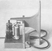
 The principle is
somewhat like an ideal speaker. No diaphragm is involved that has significant
mass or suspension stiffness. There are no resonances or transient problems.
Theoretically there is almost no limit to the frequency range and response is
inherently very flat. With a large enough horn, response was thought to be able
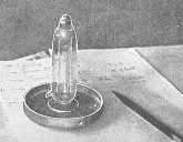
to cover the entire audio range and to well beyond 50kHz. A closeup view of the
early ionization unit is shown at the left. The opening is facing down in the
aluminum collar. A metal cathode then covers the quartz tube.
The principle is
somewhat like an ideal speaker. No diaphragm is involved that has significant
mass or suspension stiffness. There are no resonances or transient problems.
Theoretically there is almost no limit to the frequency range and response is
inherently very flat. With a large enough horn, response was thought to be able
to cover the entire audio range and to well beyond 50kHz. A closeup view of the
early ionization unit is shown at the left. The opening is facing down in the
aluminum collar. A metal cathode then covers the quartz tube.
Klein also described an excellent source of ion production using an active anode of 50% precipitated platinum, 40% aluminum phosphate, 5% precipitated iridium and 5% graphite. This active anode was excellent for ion production. In Klein's original corona discharge model a separate filament heated the anode and modulation was superimposed on a potential of 700VDC.
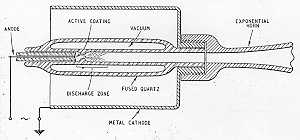 A description of how
this operates is by E. Aisberg, Publisher and M. Bonhomme, Chief Editor, both
of Tout la Radio, in the December 1951 issue of Radio-Electronics. "A high
voltage is set up between the outside cylindrical shielding and the platinum
wire which is the axis of the emitter. Through the action of dielectric losses,
the quartz surrounding the platinum wire reaches a temperature of 1,000 degrees
within one or two minutes. The strong field, which is established between the
platinum wire and the cylindrical shielding, produces emissions, which also
produce heat in leaving the emitter, thereby assisting to maintain a high
temperature. The heat is concentrated because the vacuum chamber of the
evacuated quartz horn prevents its spread by conduction. Secondarily, the vacuum
of this enclosure prevents the passage of electrical charges through the
material.
A description of how
this operates is by E. Aisberg, Publisher and M. Bonhomme, Chief Editor, both
of Tout la Radio, in the December 1951 issue of Radio-Electronics. "A high
voltage is set up between the outside cylindrical shielding and the platinum
wire which is the axis of the emitter. Through the action of dielectric losses,
the quartz surrounding the platinum wire reaches a temperature of 1,000 degrees
within one or two minutes. The strong field, which is established between the
platinum wire and the cylindrical shielding, produces emissions, which also
produce heat in leaving the emitter, thereby assisting to maintain a high
temperature. The heat is concentrated because the vacuum chamber of the
evacuated quartz horn prevents its spread by conduction. Secondarily, the vacuum
of this enclosure prevents the passage of electrical charges through the
material.
Because of the concentrated effect of heat and the electrical discharge rich in ultraviolet radiation, the emitter releases a flow of ions. The high temperature in the neighborhood rarefies the air; consequently, the molecules are far enough apart to enable the ions leaving the cathode to follow a free course longer than they could in dense, cold air. It is nonetheless true that some air molecules are ionized by collision with ions and electrons coming from the emitter.
In short, we have before us a kind of capacitor whose plates are the coated emitter with its central platinum wire and the exterior shield. Between these plates there is a cloud of ionized particles, which are in a state of agitation because they are in an alternating field which acts on all bodies, whether positively or negatively charged.
If we change the strength of the alternating electric field, we also alter the amplitude of the individual oscillations of each of these bodies. Now, molecular movement and heat are two words to describe the same phenomenon. Therefore, by varying the strength of the electric field, we can obtain corresponding instantaneous variations of temperature.
Nothing is easier to the radioman than to vary the strength of a high frequency field at a low frequency rate. The inventor of the Ionophone simply modulated his high frequency field at audio frequencies. The temperature in the vicinity of the emitter was varied in proportion to the low frequency. This takes us back to Edison's original Thermophone, with the exception that where Edison's heated wire was limited to the lower audio frequencies, the Ionophone reproduces with equal exactitude all frequencies within the audio range. (The old Thermophone produced sound by expansion and contraction of the air surrounding a heated wire, which of course had considerable thermal lag.)
Each variation in temperature produces an expansion of air, followed by a contraction, thereby producing a sound wave. These sound waves spread along the length of the exponential horn without friction and manifest their presence by sounds of the strength, form and frequency desired."
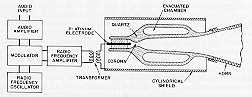 In a later model the
arc was generated by a 100kHz oscillator and then modulating it with the audio
frequency. A platinum anode was located in the center of the quartz tube. This
was connected to the high voltage terminal of a resonant coil at the output of
the oscillator. By adding a small metal strip around the outside of the quartz
tube, a blue glow discharge was caused inside the tube. When the oscillator was
modulated by an audio signal, the sound could be heard from the horn that was
coupled to it. There was a problem of audible hiss, however, that could be
heard from the corona discharge. This was found to go away when the oscillator
frequency was raised to at least 2 or 3MHz.
In a later model the
arc was generated by a 100kHz oscillator and then modulating it with the audio
frequency. A platinum anode was located in the center of the quartz tube. This
was connected to the high voltage terminal of a resonant coil at the output of
the oscillator. By adding a small metal strip around the outside of the quartz
tube, a blue glow discharge was caused inside the tube. When the oscillator was
modulated by an audio signal, the sound could be heard from the horn that was
coupled to it. There was a problem of audible hiss, however, that could be
heard from the corona discharge. This was found to go away when the oscillator
frequency was raised to at least 2 or 3MHz.
A few years later he was granted world patents. The first patent was number 2,768,246. Licenses were granted in several different countries: DuKane in the USA, Plessey Ltd. Of England, Telefunken of West Germany and Audax of France. Several problems were also overcome. One was that after a few hours of operation, the platinum vaporized and deposited on the walls of the quartz tube drawing the arc to a hot spot and reducing output.. Telefunken found that the use of a Kanthal electrode solved this problem. Kanthal is an alloy of iron, chromium and aluminum that was developed in Sweden for electrical furnace elements. It did not evaporate onto the quartz tube.
 Klein first visited
with William R. Torn in 1954 at DuKane in St. Charles, IL. Work progressed at
DuKane and the whole system was essentially redesigned based on Klein's
original ideas. Another problem was that after a few hours of use, the ionic discharge
often failed to start when first turned on. It was caused by a change in
electrical capacity of the quartz cell when the cell was discharging compared
to before discharge. If the oscillator circuit was tuned to resonance when the
cell was working, it would be considerably off resonance when the speaker was
first turned on from a cold start. Dukane overcame that problem by rearranging
the oscillator circuit so the ground electrode of the cell returned directly to
the grid of the oscillator tube. This way, although the fundamental frequency
of the oscillator changed when the discharge started, the coil continued to
oscillate more efficiently at peak resonance at all times.
Klein first visited
with William R. Torn in 1954 at DuKane in St. Charles, IL. Work progressed at
DuKane and the whole system was essentially redesigned based on Klein's
original ideas. Another problem was that after a few hours of use, the ionic discharge
often failed to start when first turned on. It was caused by a change in
electrical capacity of the quartz cell when the cell was discharging compared
to before discharge. If the oscillator circuit was tuned to resonance when the
cell was working, it would be considerably off resonance when the speaker was
first turned on from a cold start. Dukane overcame that problem by rearranging
the oscillator circuit so the ground electrode of the cell returned directly to
the grid of the oscillator tube. This way, although the fundamental frequency
of the oscillator changed when the discharge started, the coil continued to
oscillate more efficiently at peak resonance at all times.
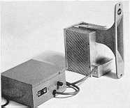
![]() The name Ionovac was
started in 1956. In 1958 Electro-Voice marketed the Ionovac under a temporary
agreement with DuKane. It sold for $147. Unfortunately, the element lasted only
200 to 300 hours. DuKane revised the Ionovac, reducing the size and weight.
Life of the quartz element was increased to 1200 hours, or about 2 years of use.
The quartz element and electrode had to then be replaced. In 1961, the cost of
a replacement element was $6.25 and was very simple to install. The Dukane
representative advised me, back in the early 1960's, that the new ultrasonic
grinding techniques would reduce the cost even more. Cost of the redesigned
Ionovac was reduced to $79 without the tweeter enclosure that is shown on the
right.
The name Ionovac was
started in 1956. In 1958 Electro-Voice marketed the Ionovac under a temporary
agreement with DuKane. It sold for $147. Unfortunately, the element lasted only
200 to 300 hours. DuKane revised the Ionovac, reducing the size and weight.
Life of the quartz element was increased to 1200 hours, or about 2 years of use.
The quartz element and electrode had to then be replaced. In 1961, the cost of
a replacement element was $6.25 and was very simple to install. The Dukane
representative advised me, back in the early 1960's, that the new ultrasonic
grinding techniques would reduce the cost even more. Cost of the redesigned
Ionovac was reduced to $79 without the tweeter enclosure that is shown on the
right.
For those who were not able to integrate the separate tweeter into their system, DuKane offered the Ionovac in complete systems as well.
Dr. Klein is also responsible for the development of the Magnat speaker first shown at the 1978 CES in Chicago. The MP88 speakers system was the first to use the MP02 plasma tweeter on the top.
![]()
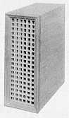
 In 1965, Fane
Acoustics Ltd., Batley, Yorkshire came out with the Ionofane 601 loudspeaker.
It is essentially a copy of the DuKane Ionovac. It comes in two parts: the
power supply and the loudspeaker, with a connecting cable in between that
allows remote placement of the power supply. The power supply comes in a metal
box containing the power transformer, modulation transformer, solid-state high
voltage supply, input level control and fuse. It measurs 5-3/8" by
5-3/8" by 2-1/2". The loudspeaker portion consists of a box with a
perforated metal cover and contains the oscillator tube, coil and quartz
element. The throat of the quartz element is 1/4" in diameter and is
directly coupled to the exponential horn that is attached to the box The
rectangular horn mouth measures 6" by 1-9/32".
In 1965, Fane
Acoustics Ltd., Batley, Yorkshire came out with the Ionofane 601 loudspeaker.
It is essentially a copy of the DuKane Ionovac. It comes in two parts: the
power supply and the loudspeaker, with a connecting cable in between that
allows remote placement of the power supply. The power supply comes in a metal
box containing the power transformer, modulation transformer, solid-state high
voltage supply, input level control and fuse. It measurs 5-3/8" by
5-3/8" by 2-1/2". The loudspeaker portion consists of a box with a
perforated metal cover and contains the oscillator tube, coil and quartz
element. The throat of the quartz element is 1/4" in diameter and is
directly coupled to the exponential horn that is attached to the box The
rectangular horn mouth measures 6" by 1-9/32".
 An EL360 pentode tube
is used as the oscillator and is screen modulation driven by a step up
transformer. This transformer has a turns ratio of 45 to 1. With this ratio, a
0.75V audio input corresponds to 34V at the screen of the pentode. It also
corresponds to 95dB sound pressure level at 18". Later models use a 6DQ6
tube and the modulation transformer turns ratio is reduced to 33 to 1. The
sensitivity is reduced to 95dB at 18" for a 1.0V input. An rf carrier
frequency of 27mHz is used. This continues to eliminate the hissing sound of
the corona. The 601 sold for 29 pounds 8 shillings
An EL360 pentode tube
is used as the oscillator and is screen modulation driven by a step up
transformer. This transformer has a turns ratio of 45 to 1. With this ratio, a
0.75V audio input corresponds to 34V at the screen of the pentode. It also
corresponds to 95dB sound pressure level at 18". Later models use a 6DQ6
tube and the modulation transformer turns ratio is reduced to 33 to 1. The
sensitivity is reduced to 95dB at 18" for a 1.0V input. An rf carrier
frequency of 27mHz is used. This continues to eliminate the hissing sound of
the corona. The 601 sold for 29 pounds 8 shillings
Fane Acoustics Ltd. Also produced the model 603 loudspeaker system that included the IonoFane. The specs are as follows:
Woofer: 15" high flux cone unit
Mid-Range: 5" with adjustable level
Tweeter: 601 ionic unit
Impedance: 15 ohms
Power Handling: 20 watts of music
Dimensions: 35" high, 22-1/2" wide and 14-1/4" deep
Price in 1966: 78 pounds 15 shillings
![]()
Questionable performance is reported in the January 1952 issue of Wireless World concerning distortion: "...it may turn out that non-linearity with consequent intermodulation is the Achilles heel of what otherwise appears to be a very promising principle". Above a 1.5V input the Ionofane and Ionovac become non-linear. Equal steps of electrical input produce less than equal steps of acoustic output. What happens when the level increases further? Initially, the distortion increases, but serious overdriving can momentarily extinguish the corona and eliminate the output. The good news is that there will be no damage to the loudspeaker if this happens.
I tested both the Dukane (Ionovac) and Fane Acoustics Ltd. (Ionofane) tweeters using a Bruel & Kjaer 1/4" condenser microphone that goes beyond 40kHz. The speakers do in fact go out beyond 40kHz and very smoothly.
Then I made one of my regular and favorite tests; intermodulation (IM) distortion. Most speaker manufacturers don't talk about distortion. Yet, it is something we can all hear if it gets too high. Even on the rare occasion that it's mentioned, tests are run at a 1 watt level and conveniently look good. However, we normally use speakers at levels higher than 1 watt. I have found that distortion in many tweeters doesn't look that good at higher power. Usually significant distortion occurs only at some frequencies and not others due to resonances, breakup, etc. Some tweeters don't survive sustained higher power tests using sine waves. I used a General Radio 1% bandwidth wave analyzer that can automatically plot the two fundamentals and all the individual distortion products. This is the method that Phil Kantrowitz and I used at Sonotone to make distortion measurements for his AES paper "Distortion Measurements of High Frequency Loudspeakers" presented in New York City convention in October of 1961.
All musical sounds consist of a fundamental and an array of harmonics. A slight amount of harmonic distortion is not that apparent in program material if it is under 1%. However, IM distortion products are more discordant and sometimes can be more easily heard. I feel that it is a better test.
The claimed 95dB level at 18" for 1.0V input seems like a conservative output level. However this translates to more like 79.5dB at 10 feet which is a normal listening distance. At a 1.5V input where distortion starts to be non-linear, the sound level at 10 feet is only 83dB. However, a level of 90dB above 3500Hz is not an unusual power demand for a good system and I consider this a minimum requirement for tweeters. In fact, levels even higher than that are needed for today's music reproduction. For comparison, a single McIntosh 1" soft dome tweeter produces a level of 90dB at 10 feet at 10 watts or 8.9V input. The Ionophone driving voltage for a level of 90dB at 10 feet would need to be 3.5V, way above the recommended level.
I decided to make some of my own tests to see for myself what would happen. Here are a few of the test results:
|
Frequency |
Input power |
Input voltage |
Distortion |
Crossover |
|
3 & 5kHz |
0.03W |
0.5V |
2.8% |
12dB/oct |
|
1 & 2kHz |
0.13W |
1.0V |
7.0% |
no xover |
|
1 & 2kHz |
0.5W |
2.0V |
5.0% |
12dB/oct |
Normally, IM distortion above 0.5% becomes audible. I tested several other Ionovacs with the same result. In comparison, the McIntosh 1" soft dome tweeter has 0.3% distortion at 90dB at 10 feet with 10 watts applied. Although a 12dB/octave crossover at 3500Hz is used, test frequencies below 3500Hz still generate high distortion. Higher frequencies show less distortion. Since most music contains less energy as frequency increases, The Ionovac seems to make a good tweeter at the very highest audible frequencies.
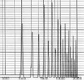 In the graph at the
right, a typical distortion array is shown. The lowest frequency is 1kHz and the
highest frequency is 20kHz. The major divisions on the graph are 15dB. In this
test two fundamental frequencies of 5kHz and 7kHz are used to drive the Ionovac
at 5V input (3.1W re: 8 0hms). The difference frequency of 2kHz has a very high
output as do the other sum and difference frequencies. Ideally, of course the
output should contain only the two frequencies that were used to drive the
speaker. I was never certain where the distortion was generated. It could have
been from the modulation transformer or the non-linear behavior of ions and the
air. The lower frequencies, which require greater ion motion also exhibit the
highest distortion, but in any case, it's all history now.
In the graph at the
right, a typical distortion array is shown. The lowest frequency is 1kHz and the
highest frequency is 20kHz. The major divisions on the graph are 15dB. In this
test two fundamental frequencies of 5kHz and 7kHz are used to drive the Ionovac
at 5V input (3.1W re: 8 0hms). The difference frequency of 2kHz has a very high
output as do the other sum and difference frequencies. Ideally, of course the
output should contain only the two frequencies that were used to drive the
speaker. I was never certain where the distortion was generated. It could have
been from the modulation transformer or the non-linear behavior of ions and the
air. The lower frequencies, which require greater ion motion also exhibit the
highest distortion, but in any case, it's all history now.
In those years some of the distortion was masked by the distortion in records, phono cartridges and tapes. Response of many record cutters and phono cartridges did not even extend as far as 20kHz. Perhaps the appeal of a near massless, resonance-free speaker with almost unlimited high frequency response overrode the reality of harmonic and IM distortion. Perhaps, also, the extended high frequency response and distortion of the Ionophone filled in the missing high frequency harmonics in the recordings. When the Ionophone was badly overdriven, the output would cease, rather than produce higher distortion and permanent damage that would occur with a normal tweeter.
I made an amusing listening test with a friend who was an Ionovac enthusiast. I had some acoustically transparent curtains in front of my speakers that sort of kept him from seeing what was playing. He thought they sounded very good and mentioned that he could see the Ionovac glow through the curtains. What he didn't know was that although the Ionovacs were turned on, they were not connected to the power amplifier. I was using a pair of ML-1C tweeters instead. The visual cue was enough to make him believe he was hearing Ionovacs. The ML-1C tweeters are 2-1/4" cone units with a 1/2" center dome radiator that extends response to 20kHz. The response is actually flatter than the Ionovac.
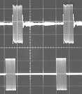 Compared to many
tweeters of the day, The Ionophone offers smooth continuous overall response
free of resonances and has excellent transients. I made several tone burst
tests. Typically they are excellent. The picture is for a 10 kHz tone burst using
a General Radio 1396-A Tone Burst Generator. The gate is closed for 64 cycles
and open for 16 cycles. The lower trace is for the input to the speaker. The
upper trace is the acoustic output from the Ionovac. Two small room reflections
can be seen between bursts.
Compared to many
tweeters of the day, The Ionophone offers smooth continuous overall response
free of resonances and has excellent transients. I made several tone burst
tests. Typically they are excellent. The picture is for a 10 kHz tone burst using
a General Radio 1396-A Tone Burst Generator. The gate is closed for 64 cycles
and open for 16 cycles. The lower trace is for the input to the speaker. The
upper trace is the acoustic output from the Ionovac. Two small room reflections
can be seen between bursts.
The response has a rising characteristic on axis. The sound generating element is a constant amplitude device. For a constant electrical input, the amplitude is independent of frequency. When this element is coupled to a horn, however, the output is proportional to the frequency. For practical systems, the amplitude is limited and restricts the use of the speaker to the higher frequencies. However, the total energy that I measure in the reverberant room is very smooth and follows the calibration fan very well. This characteristic behavior is similar to the Janzen electrostatic tweeter.
Although the oscillator is in a shielded enclosure, interference is found on channel 5 on a nearby tv set and at 103.6MHz on an FM set.
The corona discharge creates ozone that can be detected by smell in the vicinity of the speaker. In those days it was not known if ozone is harmful. By today's standards, ozone has no restrictions. However, if ozone is present in sufficient quantities (120ppb), it is known to cause eye and lung irritation. It is also known to deteriorate rubber. Watch out for those rubber woofer surrounds!
![]()
Plessey in England also invested in the Ionophone. This unit goes down to 800Hz and has a square horn mouth. It was used at the Sonotone Corporation where I worked in the 1960's. It made a good source for testing ultrasonic microphones that were being developed for use in TV remote controls.
![]()
In 1967 I experimented with beating two ultrasonic acoustic waves together and produced an audible difference frequency. I fed a fixed 40kHz audio signal to one Ionovac and swept the second Ionovac with a variable oscillator from 20kHz to 40kHz. This could be easily done with the Add 20kHz feature of the General Radio 1304-B Beat Frequency Oscillator. The difference frequency was clearly audible and I made a few response curves along with a low pass filter to limit the microphone high frequency pickup to less than 20kHz. The beat frequencies below 1kHz diminished rapidly, however, and no lows could be heard at all. Obviously there was not enough air motion generated to produce any audible low frequencies.
![]()
Electro-Voice T-3500 Ionovac Information
In 1958, Electro-Voice marketed the T-3500 Ionovac super high frequency driver under a temporary agreement with DuKane. It was used in some of the EV Patrician systems.
Copies are available for tentative specs and instructions by Electro-Voice dated December 1957. This contains 11 pages of physical and electrical specifications, theory of operation, installation instructions, operating instructions and field service information. It also contains drawings, schematics and a parts list. Copy is $6.00. For more information email to rogerr4@earthlink.net
Here's a sample of the specifications:
Response: 3,500Hz to40,000 Hz (+ or - 4dB)
Polar Pattern: 160° dispersion
Input voltage for full output: 0.64V/16 ohms--95dB at 3' from horn (average
output)
Crossover Point: 3500Hz w/12 dB/octave slope
RETMA Sensitivity Rating: 60dB
Input Impedance: 16 ohms
Maximum input voltage: 2V at 3.5kHz, 4V at 7kHz, for less than 1% harmonic
distortion.
Output: 95dB at 3' over an angle of 160°
Tubes: 1-5U4A/GB, 1-12AU7, 1-6146
Oscillator frequency: 20mHz
Line Voltage: 115VAC 60Hz with taps for 105 or 125VAC
Power Consumption: 78 watts
Fuse: 3 amp
Power Cord Length: 6 feet
RF Cable Length: 6 feet
Horn: 9-1/16" long and 1-7/8" wide
Cutout Hole for Mounting Horn Behind Baffle: 7-7/8" by 1-3/8"
Tweeter Mounting Hole Spacing: 8-3/8
Overall Dimensions of unit: 9-1/4" high, 4" wide, and 7-1/2"
deep
Overall Dimensions of Oscillator/Power Supply: 5-1/2" high, 5" wide
and 12-3/4" deep
Weight: Horn Assembly 4 lbs. Oscillator/Power Supply 9-1/2 lbs.
Shipping Weight: 16 lbs.
Finish: Chrome and Gray Wrinkle
![]()
Extending the Life of Quartz Cells
Here's a suggestion from Jack Podplesky, an Ionovac owner, that may help lengthen the life of the quartz cells. "I don't know if there are any Ionovac users this day and age, however I have found that by using a wooden toothpick and isopropyl alcohol, the quartz cells can be cleaned and reused over and over again. Just be careful not to force the toothpick into the cell too hard as I have shattered a cell trying to get a piece of wood out of the orifice. I currently use 2 pairs of Ionovacs in my dual tri-amped system and another pair with a pair of "9's" in another room. If anyone would like to contact me, my home email is jack@podplesky.net " You can also visit his web site at http://www.ionovac.com
![]()
About 1978 a company in Albuquerque, NM was selling a speaker system with an unusual driver that utilized helium to form plasma at high temperatures. this could be modulated with an audio signal. Again, the idea of a "massless" speaker having excellent transients and response was the big feature. The Hill Type 1 was first exhibited in 1978 at the Chicago Consumer Electronics Show. It sold for $5995 per pair. By 1981 the price was up to $10,000 for a pair. Only 60 pairs were reportedly ever sold. For more information about this speaker, check out The Plasma Tweeter Zone
![]()
![]()
|
More text and pictures about the
Ionophone will be added as my research continues. Any comments, corrections,
or additions are welcome. |
|
|
email to |
Created by Roger Russell |