McIntosh Loudspeaker Division Part 1
A History (1952-1975)
These pages are copyrighted.
No portion of this site may be reproduced in whole or in part
without written permission of the author.
Listed by year plus these additional subjects:
 In 1952, Mr. McIntosh had attempted to market a
speaker system called the F100. Harvey Radio advertised it in Audio Engineering
for a few months, but only five or so were sold. It contained four special
long-excursion woofers, an 8" mid-range, and four tweeters. Rudy Bozak
made the drivers. It had an overall width of 43" and a front face width of
22-1/2".
In 1952, Mr. McIntosh had attempted to market a
speaker system called the F100. Harvey Radio advertised it in Audio Engineering
for a few months, but only five or so were sold. It contained four special
long-excursion woofers, an 8" mid-range, and four tweeters. Rudy Bozak
made the drivers. It had an overall width of 43" and a front face width of
22-1/2". 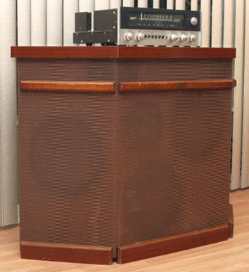 Height is 30". Power rating was 50
watts and impedance was 8 ohms. The advertised price was $374.50 in either
blond or mahogany finish.
Height is 30". Power rating was 50
watts and impedance was 8 ohms. The advertised price was $374.50 in either
blond or mahogany finish.
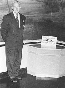
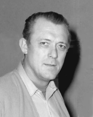
No further attempts were made to sell loudspeakers until I was hired. Mr. McIntosh gave me the photo at the left many years ago.
Here is a rare picture of an F100 system (right) owned by Bruce McIntosh (grandson). I think it is only one of two known F100 systems that still exist today.
That is a MAC1700 receiver sitting on the top of the system. Many thanks to Bruce for the picture.
1967
This year marks the beginning of the
McIntosh Loudspeaker Division. I was hired in March to create a series of
loudspeaker systems that would introduce an entirely new product line for
McIntosh. This was an opportunity for me to continue with my fascination with sound and search for better
ways to increase accuracy and expand the listening experience.
In a way, speakers are much more complex than amplifiers or preamplifiers. With electronics, you can put the unit on a bench and attach oscillators, meters, etc. and you have the performance pretty well tied down. In speaker design, there is not only an electrical system having resistance, capacitance and inductance but there is also mechanical and acoustical systems, each having equivalent reactive and resistance elements. What's more, these can interact with each other and the room. Due to the complexity of speakers and speaker systems, design turns out to be partly an art and partly a science.
The formal name for a speaker is an electro-mechanical transducer. This covers not only speakers but also other devices that convert energy from one system to another—such as microphones or phonograph cartridges. Good speaker designers are hard to find and conversely, jobs for these designers are also hard to find.
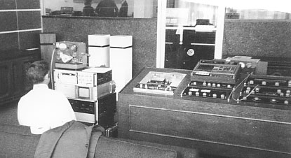
An addition to the main plant was completed early in the year for the acoustics lab. Although my first priority was to design the C26 Stereo preamplifier that was immediately needed to replace the C24 preamp, I also began planning procedures and assembling test equipment needed to run the speaker research and development.
The acoustics lab consisted of a reverberant room and a small listening room. The reverberant room was made entirely of concrete, including the ceiling. The walls were coated with hard plaster and then painted with epoxy paint to be as reflective as possible. The dimensions of 16' by 13' and a 10' high ceiling were proportioned to give useful measurement down to 250 Hz. With the use of a calibration fan, I was able to measure even lower. The purpose of a reverberant room was to sum up the total energy that a speaker radiates regardless of its directional properties. The test could be used to measure acoustic power. The speaker and microphone are not located near each other, however, for this to work properly.
The test equipment was made by General Radio and consisted of a 1564 sound and vibration analyzer, 1521-B chart recorder, 1304-B oscillator and 1900 wave analyzer. Although the GR test equipment I used back then could be thought of by today’s computers as antique, it was never-the-less just as accurate and even had some advantages. However, the time needed to run the tests was definitely longer. Bruel & Kjaer 4133 and 4134 microphones were used. The 4134 was a random incidence microphone used for the diffuse field measurements in the reverberant room. The 4133 was for free field measurements. Because the microphone response was flat beyond 20kHz within a few tenths of a dB, a correction curve for speaker measurements was not needed. Photo courtesy of Dave O’Brien.
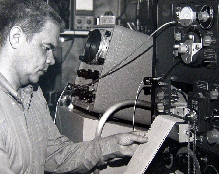
While finishing up the C26 Preamp, several months were devoted to making a thorough evaluation of the many different kinds of speaker systems and drivers we had bought or borrowed. The listening test was first. I felt this might avoid any bias from measurements that were made later. Because distortion, response and impedance curves were very time consuming to run. I was able to borrow Vince Wallace (below) from production now and then to make some of the tests. Here is Vince working on an MC3500 power amplifier in production. He seemed very quiet and reserved but at the company Christmas parties he was a very outgoing Santa Claus and handed out the presents.
My investigation of various drivers ranged from inexpensive to exotic things like the Kelley ribbon horn and the Ionovac tweeter. I compiled a history of The Ionophone loudspeaker and made intermodulation distortion (IM) tests to see if it was really that good. I used closely spaced frequencies to make loudspeaker tests. In electronics, IM tests were often made with one low frequency and one high frequency. This, of course was not useful to evaluate drivers that covered only a narrow frequency range. My first experience with close frequency IM tests for tweeters was in 1960 when I worked with Phil Kantrowitz at the Sonotone Corporation in Elmsford, NY to gather data for his Audio Engineering Society (AES) paper. It was presented at the Thirteenth AES Convention in October 1961 titled "Distortion Measurements of High Frequency Loudspeakers." Many of the systems I tested showed performance defects either in the reverberant room tests, free field, distortion, impedance, etc. After reporting findings to Gordon Gow, he concluded that ordinary drivers, when designed and used properly, were the way to go.
1968
I hired Bob Campbell this year as a permanent assistant to help with some of the work in assembling prototype cabinets and making response curves. Bob had retired from the Air Force and was very pleasant to work with. I was the only engineer that was able to hire an assistant but then speaker work was very different from electronics.
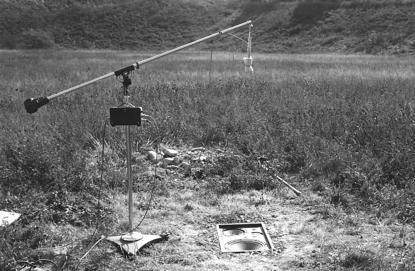
To confirm the low frequency measurements that I made in the listening room, I decided to make measurements outdoors as well. Bob dug a hole in the field about 50 feet from the main plant. The speaker was buried flush in the ground to simulate radiation into a solid angle of 180 degrees. It was buried to avoid sound reflecting from the ground and interfering with the direct radiation from the woofer.
We encountered a surprising amount of background noise from cars, insects and even beetles that managed to get on the woofer cone and bounce around. Open pore acoustic foam was wrapped around the microphone to prevent wind noise from interfering with the measurements. The microphone was located at various heights up to 10 feet. The microphone power supply is hanging from the boom stand.
![]()
 I designed my first elaborate speaker system at home
back in the early 1960’s. This was while I was working at Sonotone. We had
found the AR-3 dome tweeter to have very low distortion. Ed Villchur at AR was
very pleased with our findings. We also found the AR-3 woofer to also have very
low distortion. I arranged with Ed to purchase two 5/8” excursion woofers for
my own system and drove to 24 Thorndike Street in Cambridge to pick them up.
I designed my first elaborate speaker system at home
back in the early 1960’s. This was while I was working at Sonotone. We had
found the AR-3 dome tweeter to have very low distortion. Ed Villchur at AR was
very pleased with our findings. We also found the AR-3 woofer to also have very
low distortion. I arranged with Ed to purchase two 5/8” excursion woofers for
my own system and drove to 24 Thorndike Street in Cambridge to pick them up.
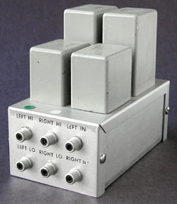
Because I was still enamored with the Lowther drivers at that time, I arranged with Donald Chave at Lowther in England to send me a pair of PM-4 drivers. The efficiency of the PM-4 was much higher than the AR woofer so I thought I would try an electronic crossover and separate amplifiers to drive each of the speakers. Although a Heathkit electronic crossover was available at that time, it did not roll off the speakers fast enough. The Lowthers were designed to cover a much wider frequency range than what I had in mind. I decided to use something with a sharper rolloff. This was the UTC Butterworth filters that roll off at 60 dB per octave. The crossover was at 500Hz and I used LMI-500 filters for the low pass and HMI-500 filters for the high pass.
The graphs I made look like the curves roll off straight down, but of course, no filter rolls off that fast. What I learned from this experiment is that a better and simpler crossover design can be used when the drivers have their own inherent passband characteristics. Ideally, the driver output increases, is flat through the desired passband and rolls off without any crossover at all. Of course, no driver is perfect and a supplementary one is still needed to trim the response. However, the number of elements and complexity of the network can be greatly reduced. The natural rolloff of the driver combined with only a moderate crossover rolloff is more than adequate and the more complicated and expensive 60dB/octave network is not needed.
![]()
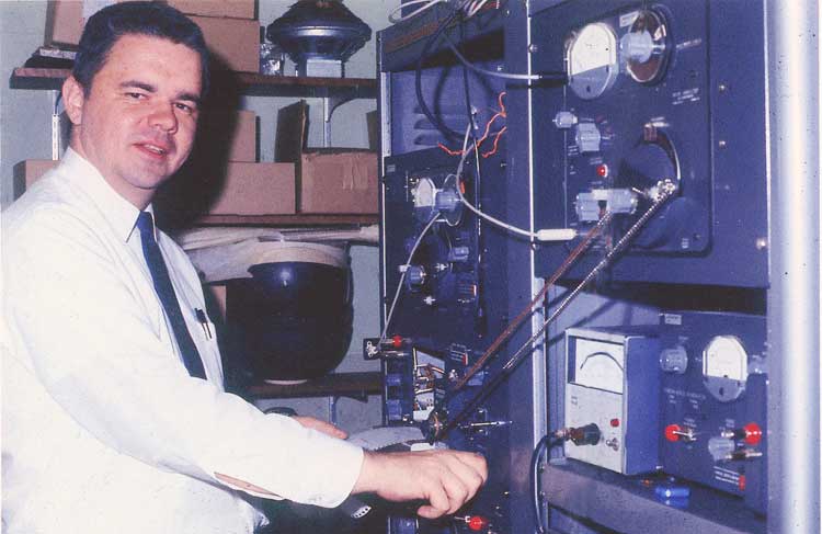
In 1968, I was to fulfill another dream. Since working with General Radio acoustic test equipment at Sonotone, I always wanted to have my own test equipment so I could do measurements at home. One day, when the GR representative was at McIntosh, I asked him about availability of used equipment and it turns out that I was able to purchase the long sought-after 1521B Graphic Level Recorder, 1564A Sound and Vibration Analyzer and 1304B Random Noise Generator with pink noise filter. I started with a GR 1304A beat frequency oscillator but later replaced it with a more recent GR 1304B model. The oscillator and analyzer were chain driven and the chart paper speed matched the sweep speed.
The analyzer is great for response measurements and can filter wideband pink noise continuously with either a 1/3 octave or 1/10 octave class III filter. Using noise reduces annoying acoustic peaks and dips encountered with sine wave sweeps. However, for other applications such as close microphone, impedance curves or other audio equipment, sine wave is the preferred choice.
I had already bought a Hewlett Packard 122B dual trace oscilloscope while working at Sonotone. This had replaced a Heathkit scope that I had previously assembled. I had also made an oscilloscope cart to hold the scope. I also bought a Bruel & Kjaer 4133 condenser microphone and fet preamplifier to go with a used B&K power supply. To accompany this was a used Ballantine AC voltmeter. This has the same scale as the Ballantine meters used at Sonotone and has a linear dB scale that is much more useful. It replaced an Eico 250 AC voltmeter.
Here I am at home running response curves in my basement lab.
![]()
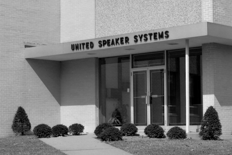
United Speaker Systems
The ML-1C went into production this year. However, we were not able to manufacture or assemble the speaker systems at this time. It required extra space, personnel, magnetizer, etc. We contacted Bill Hecht, President of United Speaker Systems, to see if he would be interested in making speakers for us. Bill was able to manufacture both drivers and crossover networks. He even had a large magnetizer and had been very successful in making a wide variety of speakers for Avery Fisher over the years. The plant was located at 192 William Street in East Orange, NJ not far from the Garden State parkway.
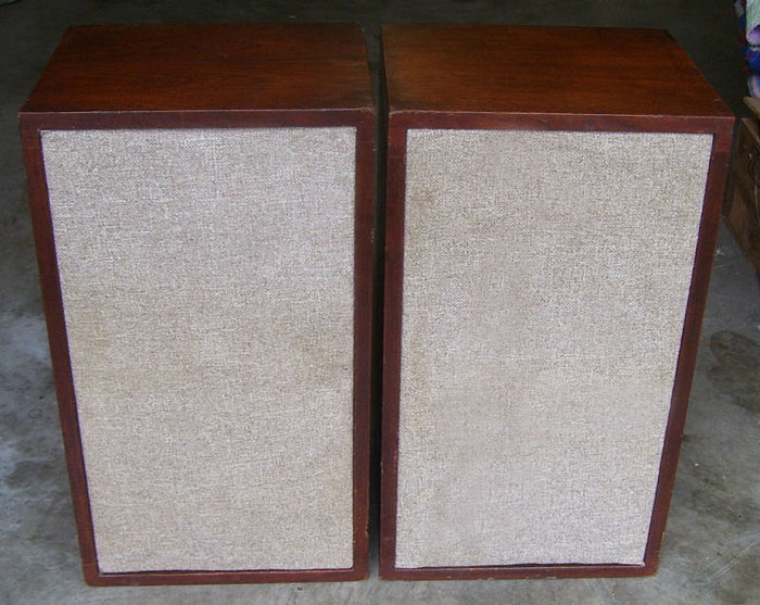
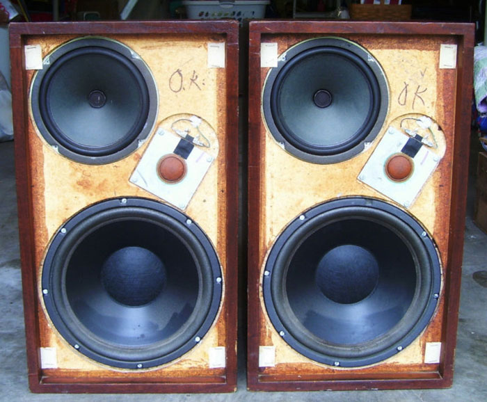
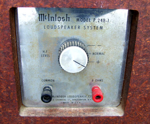
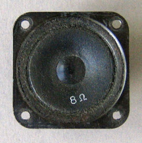
My initial design had a 12” woofer, an 8” mid-range and a tweeter as a “bookshelf” system. Several cabinets with different appearances were constructed. Bill made them into finished systems using his version of the drivers and crossovers that he could conveniently make. The project number of one design was P248-1. There were also dash 2 and dash 3 systems made as well as P249 systems. This is what the P248-1 looked like.
The soft dome tweeter was patented by Bill Hecht. The domes were made of cotton cloth impregnated with phenoloc material and then formed by a hot press into the dome/surround shape. As I recall, the dome pieces were made by NuWay in Chicago. After forming, there were still tiny holes in the dome material and Bill used butyl rubber dissolved in toluene to paint on and that covered the interstices.
Of course, Gordon Gow was not satisfied with the appearance and located Warren & Friedman to come up with alternate appearance designs. They made designs for the Drexel furniture line. Meanwhile, I was not satisfied with the sound that might have been more like speakers he made for Fisher. Bill had used an overdamped woofer but the crossover rolled off the high end very early resulting in a response that peaked up in the 50-60Hz area. It gave an emphasis to the bass but did not work well with some program material.
Without the peaked output in the 50-60Hz area, an overdamped could be used to have higher output in the upper bass range and could then cross over to a mid and tweeter that could also have higher output. Of course, an overdamped woofer has less relative deep bass output. Bill had used a two layer 2-1/2” voice coil in his Alnico magnet structure. I decided to use a high-power guitar woofer that had a large barium ferrite magnet. It also had overdamped response. This sample was from CTS in Padukah, Kentucky. So I thought that if I converted the phono section of my C26 preamp design to make an equalizer, it could correct for the response. It could not only extend response flat from about 200 Hz, where it began to roll off but also extend it through system resonance and continue on down to 20 Hz within 1dB. No other speaker system could do that. The high frequency level switch in the back of the system was no longer needed. I incorporated that feature plus a mid-range control in the equalizer. I also decided to use a higher power 8” mid that was also from CTS. I fitted it in a Sears “Bongo” salad bowl to isolate it from the woofer. See my page with more details about The ML-1C and the Equalizer Concept
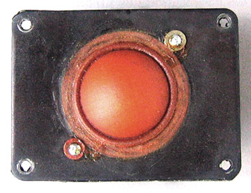
I decided to use Bill Hecht’s 1-1/2" soft dome "tweeter" but requested the front plate size to be reduced from 4” by 4” down to 4” by 3”. The dome did not extend response to 20kHz, particularly off axis. I added a supplementary tweeter crossing over at 7kHz to solve the problem. The tweeter was made by Peerless of Denmark, formerly known as Royal Copenhagen. I had used the Royal MT-20 tweeter in my RM-1 system at Sonotone. Since then, a new Peerless MT225HFC tweeter had been introduced. It had much better response and directional characteristics. The thin 1/2" aluminum diaphragm in the center extended response to 20kHz.
 So with the design of the cabinet appearance,
high-power woofer, equalizer, high power 8” driver, additional tweeter and new crossover,
the ML-1C was born. The cabinets were made by Arnold Furniture in New Jersey.
The drivers and systems were assembled to our specifications at United.
McIntosh, of course, manufactured the MQ101 equalizer. United Speaker Systems
is now known as Phase Technology in Jacksonville, FL. Bill's son, Ken, is now
President. The prototype P248 and P249 systems were auctioned off to McIntosh
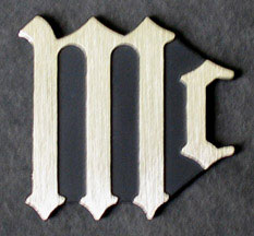
employees. The unique Mc logo appeared on the first McIntosh loudspeaker
system, the ML-1C. It was used only on the speaker systems and was used until
1992. The full name of McIntosh was used thereafter, starting with the XR290.
So with the design of the cabinet appearance,
high-power woofer, equalizer, high power 8” driver, additional tweeter and new crossover,
the ML-1C was born. The cabinets were made by Arnold Furniture in New Jersey.
The drivers and systems were assembled to our specifications at United.
McIntosh, of course, manufactured the MQ101 equalizer. United Speaker Systems
is now known as Phase Technology in Jacksonville, FL. Bill's son, Ken, is now
President. The prototype P248 and P249 systems were auctioned off to McIntosh
employees. The unique Mc logo appeared on the first McIntosh loudspeaker
system, the ML-1C. It was used only on the speaker systems and was used until
1992. The full name of McIntosh was used thereafter, starting with the XR290.
Starting with the ML speakers, all response claims were for 20Hz to 20,000Hz. A tolerance of + or- so many dB was not given. Although the woofer response was flat to 20hz, I did not guarantee that a customer would get response within certain limits at any particular point in their listening room. This was particularly true at low frequencies. Room acoustics play a major role in the apparent response of a speaker. This is determined by room dimensions and construction. Different rooms, of course, will have a different influence on the same speaker system.
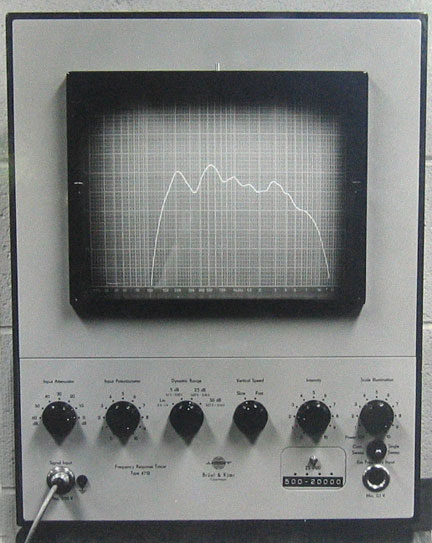
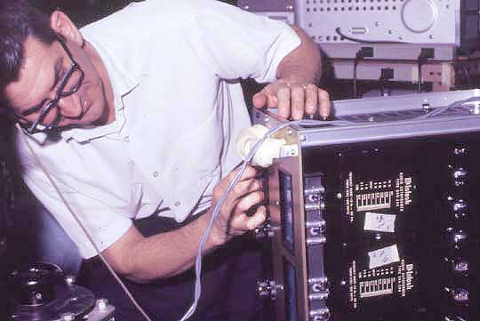
United did not have adequate test equipment to assure uniformity of each driver that they had manufactured. We loaned them a Bruel & Kjaer 4712 Frequency Response Tracer, 4133 microphone, 2801 power supply and HP sweep oscillator to insure uniform response quality for the individual drivers and crossovers they made for us. The curve automatically displayed the response of the driver as the oscillator slowly swept the frequency range. Different plug-in modules covered different parts of the frequency range. The response of this driver in the display was influenced by the test enclosure for the driver so standard drivers were provided that had been tested in free field conditions in the lab. As long as the production matched the standard within acceptable limits, production drivers were acceptable. A crayon marker could be used to mark the limits on a transparent insert placed over the screen
![]()
With the completion of the C26 preamplifier and addition of more engineers, I moved my desk and test equipment into the listening room. By this time, Sidney and I were looking for a bigger place to expand the speaker lab. Eventually, the listening room became the new computer room and the reverberant room was divided into two offices, one for Jean Filon and one for Mike Paiva.
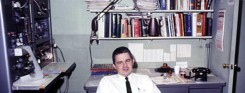
Young engineer suffering from listener fatigue in a room with poor acoustics.
![]()
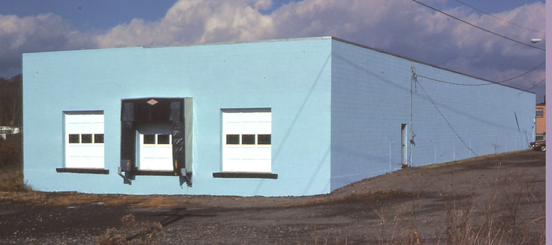
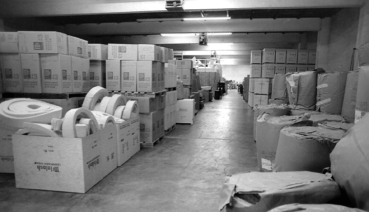
In the summer of 1970, the acoustics lab was moved from the main plant to a 10,000 square foot facility called plant 5 at 1290 Arterial Highway in Hillcrest. This was about 5 miles north of the main plant in a group of trucking terminal buildings. The building was rented by McIntosh. It was built by Cliff Signor, who owned the Albany-Binghamton trucking lines. The roof came from the old Arlington Hotel in Binghamton. The building was previously a storage facility and had been filled with thousands of gallon containers of Elmer’s glue. For McIntosh, it served as a warehouse where finished goods were stored and shipped plus our acoustics lab. Loading docks were at the south end of the building.
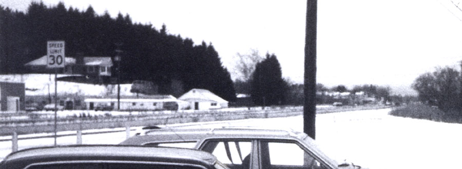
Here is one of those cold snowy days. This view is looking south from Plant 5 with the Brandywine Highway and the Arterial Highway side road. Across the street are some one-story apartments. Much further down is the Hillcrest Shopping Center with a few stores like the Great American supermarket and Nelson Ellis furniture store.
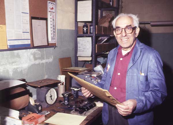
Shake (Blanen Baroa) was also transferred to plant 5 to handle the shipping of all finished goods. Jim Kane handled the fork lift but after he left, Jim Melody took over. All the units were placed on wooden skids and stacked floor to ceiling. Here are some ML-1Cs being stored. Placing the skids on the simple steel framework was a little tricky but the boys were good at it. The fork lift was very heavy.
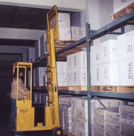
I remember one time when Jim was driving the lift into a long trailer truck to pick up some skids, the front wheels went through the floor of the trailer. We had to wait for the company truck to bring over some long Johnson bars and all of us had to lean on them to pry the lift up and back to get it out of the trailer.
The building wasn’t much to look at from the outside but the lab rooms inside the building were all finished very nicely. There was a listening room, reverberant room, test room, office space and rest rooms. I couldn’t resist putting signs on the doors of the rest rooms. Instead of saying men and women, I put “woofers” and “tweeters.” This caused a little confusion with some of the visitors but at least it was educational.
I was the responsible manager for the building. This included making sure there was sufficient propane gas for the heaters in the winter. The main building was not well insulated and we went through 1500 gallons of LP gas every three days when temperature went below zero. We also had an alarm system that failed now and then and I sometimes needed to find the defect and temporarily bridge across it until the service man, Lou Stantz, could get there the next day. I also made sure Ed Fendick got there with his snow plow before noon time so the McIntosh truck could get to the loading dock. I was usually the one that shoveled out the entrance to the building in the morning so we could get our cars off of Arterial Highway. I enjoyed having my own building to manage.
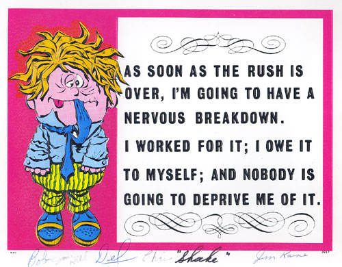
As both building manager and loudspeaker engineer I guess I didn’t notice that I looked so busy but the people who worked for me noticed. It was very thoughtful of them to give me this card with all of their signatures. There were seven of us all together at that time in plant 5.
The listening room is improved over the one in the main plant. The room is proportioned to distribute standing waves at low frequencies as evenly as possible throughout the spectrum. It measures 19'-6" by 25' and 7'-6" high. Although the walls defining the listening room are concrete block, interior walls are made using 2X4's spaced away from the block by one inch. Fiberglass insulation is put between the 2X4's and the walls are covered with sheet rock, making it very similar to home construction. This construction allows the walls to move, absorb some of the energy, and greatly reduce the amplitude of the resonances that remain. The ceiling is 2X12's covered with sheet rock. A plywood floor is added on top of the 2X12's and is used for storage above the room. A durable carpet with foam rubber backing is installed on the floor.
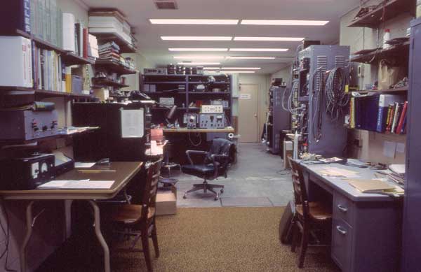
The lab area contains all of the desks, work bench, test equipment and storage shelves. This is the view taken from my desk that was at one end. This area is almost as large as the entire engineering section at the main plant.
The reverberant room is identical to the one at the main plant. The test room is for quality control inspection and testing of the ML-1C's. A spray type humidifier system is added to keep the humidity in the rooms higher during the winter months. Without this, the difference in absorption could change the response in the reverberant room by as much as 5 dB at the higher frequencies. A water filter is used prior to the humidifier to remove calcium from the water. Otherwise a fine calcium dust would appear on everything in the lab and possibly get into the test equipment. An area out in the main building is used for wood cutting and prototype cabinet construction.
McIntosh P349 Loudspeaker Switching Console
Although the ML-1C is more efficient over most of the frequency range, it has less relative output in the deep bass range compared to other systems. The equalizer provides the other half of the design to achieve an outstanding bass response to 20Hz that no other system that size can reproduce by itself. A required equalizer could have been a problem to demonstrate the ML-1C in stores. A solution for McIntosh dealers was the P349 Loudspeaker Switching Console.
 The P349 is a switching
device that allows the user to select any pair of loudspeakers from a total of
8 pairs. All pairs are driven from a single program source consisting of a
preamplifier and power amplifier. The McIntosh MQ101 and MQ102 or equalizers of
other manufacturers can be connected between the preamplifier and power
amplifier on any of the 8 speaker switch positions. Slide switches on the rear
of the chassis can be set to by-pass the signal for speakers that are not
designed to operate with an equalizer. Individual level controls are provided for the left and right
channels for each speaker selector so they can be adjusted for equal acoustic
output from each speaker.
The P349 is a switching
device that allows the user to select any pair of loudspeakers from a total of
8 pairs. All pairs are driven from a single program source consisting of a
preamplifier and power amplifier. The McIntosh MQ101 and MQ102 or equalizers of
other manufacturers can be connected between the preamplifier and power
amplifier on any of the 8 speaker switch positions. Slide switches on the rear
of the chassis can be set to by-pass the signal for speakers that are not
designed to operate with an equalizer. Individual level controls are provided for the left and right
channels for each speaker selector so they can be adjusted for equal acoustic
output from each speaker.
Speaker switch contacts have heavy-duty solid silver contacts rated at 6 amps, which can handle large amounts of audio power. The switch positions are inter-locked so that only one pair of speakers can be played at a time. The speaker grounds for the left and right channels are isolated from each other. An additional P349 console can be connected to the first console to expand the switching system to 16 pairs of speakers. An 11-pin socket at the rear panel provides 6.3 volts for lighting lamps that can be located on the speakers to indicate which speakers are playing. Pin #1 is for position #1, pin #2 is for position #2, etc. Pin 10 is a common ground.
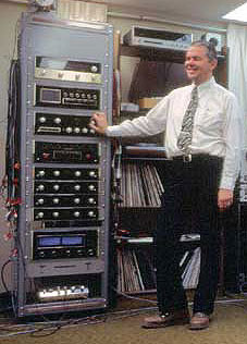
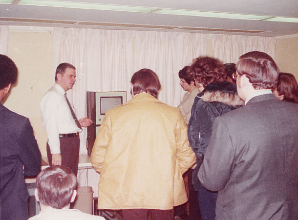
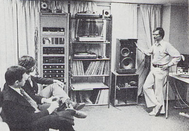
Here I am demonstrating the ML-1C in our listening room at plant 5. Four MQ101 equalizers are mounted under the console to be used with McIntosh speakers. When recordings containing deep bass are played, the benefits of the ML-1C system can clearly be heard.
To further complicate matters, the equalizers were sold separately from the speakers instead of being included in the price of the system. This was a fatal mistake to preserve the integrity of my design. The equalizer was treated as an optional enhancement instead of an essential part. Granted, the MQ101 selling price of $250 would add more to the cost of $624 for a pair of ML-1C systems. However, the alternate is the MQ102 equalizer that provides the same required low frequency equalization but without a high cost. It had a price tag of only $74.50.
![]()
The new listening room is also used for lectures and demonstrations. Gordon Gow, or a McIntosh representative, often bring in a group of visitors for a tour of the acoustics lab at Plant 5. Some are various McIntosh dealers, reporters from publications or customers. Occasionally there are groups of up to 20 to 30 from Europe or Asia. I am informed ahead of time that a group will be on the way and we arrange extra chairs in the listening room.
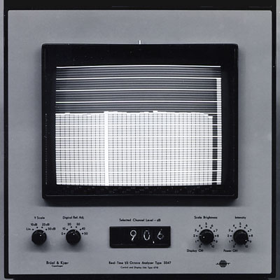
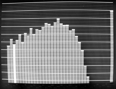
Analyzer Display Portion
I set up a demonstration showing our new $20,000 Bruel & Kjaer 3347 real time analyzer and how it works for our acoustics research. The advantage is that all the 1/3 octave frequency bands can be seen at the same time. By using pink noise from a generator, all of the bands show the same amplitude. Pink noise is constant energy per octave. At lower frequencies, a 1/3 octave band is much narrower than higher frequencies so a longer averaging time is needed for an accurate reading. A simple formula for averaging is BT, the product of bandwidth and averaging time.
The 1/3 octave bands run from 12.5 Hz to 40 kHz. A single band can be highlighted for a numerical readout. The right hand column is the input level to the analyzer. The major horizontal lines are 5 dB increments and the minor lines are 1dB. The display can be photographed or printed out on the Bruel & Kjaer 2305 chart recorder.
In addition to speaker measurements the analyzer is very helpful to supplement speaker listening evaluations. By driving a speaker with pink noise and holding a microphone in various places, it is easy to locate frequency bands where response problems are heard. This instant feedback is very helpful.
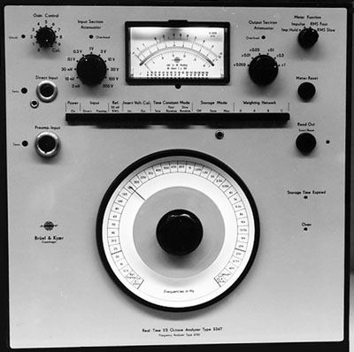
Analyzer Control Portion
For an introduction to what random noise is like, I connect the TP1 output jack on an MR71 tuner to the analyzer. This displays FM inter-station hiss prior to the tuner de-emphasis network and is called white noise. White noise is defined as constant energy per cycle. It is seen on the analyzer as a rising characteristic of 3dB per octave. The bandwidth for a 1/3 octave filter increases with increasing frequency.
As an interesting side note, turning the C26 preamp bass control all the way up and the treble control all the way down I get what I call poor man’s pink noise because it is sounds much like pink noise but is not as accurate. The pink noise we use for measurement of speakers is nothing more than a random white noise generator with an accurate filter. I use pink noise for many different measurements and even to supplement speaker listening tests.
|
|
|
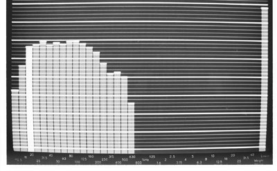
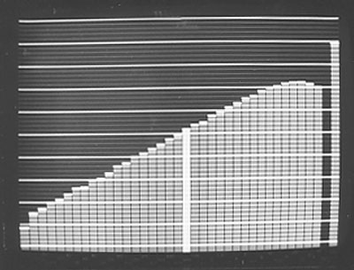
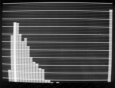
Using pink noise, I show the response of the ML-1C woofer with a close microphone technique. Without the equalizer (left), it rolls off starting about 150 Hz. With the equalizer (right), response is within 1 dB from 20 Hz up to 250 Hz and that is where the woofer crosses over to the mid-range. Remember that the first two bands are for 12.5 Hz and 16 Hz and the equalizer is designed to roll off below 20 Hz. The 20 Hz band is highlighted.
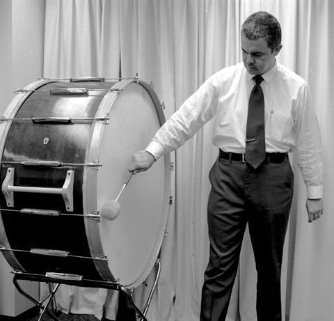
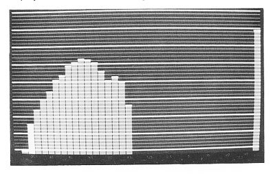
Jim Carroll arranged to rent some musical instruments for us to evaluate. The kettle drums didn’t go low enough in frequency to make a good demonstration. I decided to show the spectrum of a strike on our bass drum using a Bruel & Kjaer microphone and the analyzer in the peak hold mode. Prior to the visitors arriving, I had tuned the drum for a 25Hz fundamental. Frequent tuning was essential as the tension was greatly influenced by temperature and humidity. The demonstration establishes that real musical instruments do indeed have acoustic output at very low frequencies. With the flat response of the ML-1C and equalizer combination, the drum strike can be reproduced very accurately.
I use an MC2300 amplifier to show how speaker distortion at 25 Hz can also be displayed on the analyzer. With 100 watts of sine wave into the ML-1C, the fundamental and harmonics are displayed on the screen. The only significant harmonic is down 30 dB and is the same as 3% distortion. Then I connect a Bose 901 speaker system and put the same signal into it. The Bose system is less efficient than the ML-1C and requires turning up the amplifier level until the 25Hz fundamental on the Bose matches the output of the ML-1C fundamental. This requires several hundred watts but by then the Bose distortion products are higher than the fundamental or 100% distortion. The visitors are impressed. Then I play music through the ML-1C systems. I had previously selected ten different records that have significant low frequency output. I used some of these to demonstrate the ML-1C low frequency capabilities.
|
The
Fox Touch |
Dark
Side of the Moon |
Mormon Tabernacle Organ |
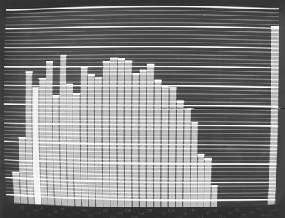
Here are three examples. Using the peak hold feature on the analyzer, a short sample can then be displayed on the screen. The 31.5 Hz band is highlighted. To the left of that is 25 Hz and then 20 Hz. The output of a C32 phono section is directly connected to the Bruel & Kjaer analyzer. Dr. Fletcher might have loved to have had one of these analyzers considering how much time and effort was needed in the early days to accomplish similar results for musical instruments.
Of course, an advantage of the MQ101 is not only to supply the necessary low frequency contour but also allows the mids and highs to be adjusted as well. This can be done near the preamplifier or receiver instead of reaching behind the speaker and turning controls or switches. Also, where power is concerned, contact resistance is critical. Controls and switches in a speaker system can become intermittent over time and cause distortion.
After my presentations but before the groups leave, I answer any questions.
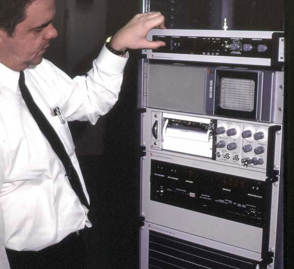
I also give lectures about another piece of our test equipment. This is a General Radio setup. The top unit is a microphone preamplifier that is used to power six Bruel & Kjaer 4134 microphones. Then there is an oscilloscope display. Below that is a position servo chart recorder, then a master control unit and at the bottom is an adjustable 1/3 octave filter. The advantage for this is to be able to record six different microphone positions at the same time, average the response and then make a single 1/3 octave response plot. Care has to be taken to calibrate each microphone output with a Bruel & Kjaer piston phone. The output sensitivity of each microphone cartridge is slightly different and calibration controls are provided in the preamplifier. The 4134 random incidence microphones are selected because they are to be used in a semi-reverberant environment.
|
Setting up for tests at Purdue Radio in New Jersey. |
Measurements
made at Clark Music
|
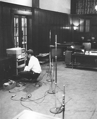
This test equipment is very useful to gain first-hand knowledge about the influence of different rooms on the response of the McIntosh systems. This is particularly important because our systems are uniquely capable of response down to 20 Hz and even lower. We measure rooms in several different homes including those of Gordon Gow and Mr. McIntosh. We also travel to several different dealers to measure showrooms including Audiocraft in Cleveland, Clark Music in Syracuse, David Dean Smith in New Haven and Purdue Radio in New jersey. The microphones are pointed face-up and are set at two different heights approximating sitting and standing positions. Different arrangements are used around the speakers and rooms. The information we gain eventually leads to the development of the MQ104 environmental equalizer that provides filters to correct for room resonances. A more detailed explanation about this work and room resonances can be found on my page about rooms.
I was also guest lecturer at Broome Tech a few times. That was for electronics students so emphasis was entirely different than for the visiting groups. There I discussed electrical fundamentals like magnetism, crossover components and how a speaker works. Of course, I supplied plenty of McIntosh literature at the end.
![]()
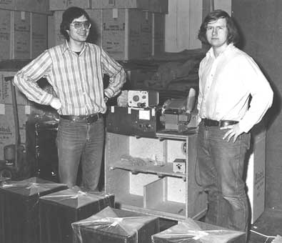
The ML-1C's sold very well. We were opening testing and re-packing 50 systems a week. It had become necessary for me to hire more personnel to handle and inspect the systems. Here are two of the system testers, Jim O'Dea and John Knapp.
Here is Jim Hill putting the final touches on the ML-1C systems. A form is filled out for each system that describe any defects that are found in the systems. This information is sent back to United Speakers.
In addition, there are quality control people from the main plant. By 1971 there are nine people working for me, including three in the research area. We also add the ML-2 and ML-4 floor standing systems, which are initially built by United Speaker systems. The floor systems are made in a contemporary style similar to the ML-1C. The ML-2C has two 12" woofers and the ML-4C has four 12" woofers. The floor systems are also made in a Mediterranean style, the ML-2M and the ML-4M. The Mediterranean systems are available with pleated red, green or gold cloth curtains behind the grilles. The equalizer is also required for these systems as well.
Equipment consoles of similar height and depth to the floor systems are also made in both styles.
The ML-4's are capable of handling large amounts of power with low distortion. The four 12" woofers are superior to two 15" woofers. The total moving cone area is greater and there are four voice coils to dissipate heat instead of two. A favorite demonstration of mine is to plug the ML-4 woofer section into the 120-volt wall outlet. This really captures the attention of visitors who question the power handling of the system, and it is also very loud. Although this demonstration is impressive, the actual power delivered to the woofers at 60Hz is not that great. The impedance of the system at that frequency is about 30 ohms and the current is only about 4 amps. Had the line frequency been at 120Hz where the impedance is 10 ohms, it could have burned out the woofers. I had also disconnected the mids and tweeters. The harmonics from the transient current might have damaged them when the system was first connected to the line.
1971
To introduce the new McIntosh speaker line,
Gordon Gow presents several loudspeaker seminars at various dealers. 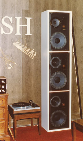
|
Seminar at Audiocraft Co |
Perhaps this stack of three ML-1C systems is a forerunner to column systems but is created to handle the power from the new MC2300 power amplifier. Several people suggested stacking three ML-1C’s for louder sound and requiring very little floor space. A special pair of white Formica cabinets are made for one of the shows where the ML-1Cs could be placed inside. It is a great demonstration with the MC2300 to drive them.
A grille with black cloth is provided and is leaning against the cabinet. Two such columns of ML-1C’s are donated to Roberson Center for arts and science in Binghamton for their auditorium. However, no cabinets are provided. Two lengths of wood are screwed to the back of the cabinets to hold the stack together and the original ML-1C grilles are used. A power amplifier and preamplifier are also included in the donation. The auditorium featured a restored Link pipe organ.
1972
This year we start to assemble ML-2's
and ML-4's at plant #5.
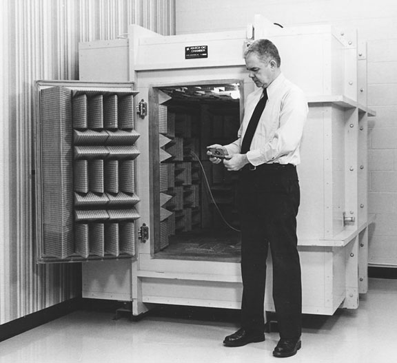
A more controlled environment is needed to do more accurate and repeatable tests for drivers. We are able to purchase an Eckel portable anechoic chamber that has a cube-shaped internal useable space 45" on a side. The word anechoic means without echo or reflection. Fiberglass wedges are used to absorb 99.9% of the sound striking them. The wedge dimensions determine the lowest frequency limit. The wedges are 12" long, which correspond to 1/4 wavelength, for a cutoff frequency of 250 Hz. It arrives in three sections that have to be bolted together. The whole chamber weighs 3000 lb. and rests on rubber shock mounts. It cost about $9000 at that time. We use a pallet hauler to lift the assembled chamber and position it on the shock mounts.

We also invest in some Bruel & Kjaer acoustic test equipment. This includes a 2305 chart recorder, 2607 measuring amplifier, 1022 oscillator and 2020 slave filter. The slave filter enables us to make continuous harmonic distortion measurements. This is very important in loudspeaker work. In electronics you can measure distortion at 20 Hz, 1kHz and 20kHz. If it's low you can accurately infer all frequencies in between are equally low. In speakers this is almost never true. Resonances and breakup can occur at any frequency and not show up at others. Shortly after that we add a Bruel & Kjaer 1901 tracking frequency multiplier. This unit enables us to resolve the harmonic distortion measurements into continuous individual distortion curves--second, third, etc. This measurement technique is essential in the development of the LP/HP woofer by Carl Van Gelder in 1992.
About this time McIntosh begins offering speaker clinics to a few selected dealers. Gordon Gow conducts them almost entirely. The tests are made on any speaker brought in to the clinic, regardless of manufacturer. There are three different measurements. The first is a distortion versus power test at a frequency of 25.7Hz, A4 on the music scale. Power measurements are made up to 100 watts, or until the speaker distortion exceeds 30%. The second is a low frequency response curve of the woofer from 25Hz to 500Hz. The third is an impedance curve from 20Hz to 20kHz.
When McIntosh speakers were tested, the required equalizer is used and response continued within 1 dB right down to 25Hz, the lower limit of the graph. No other system was able to do this. Many other brands go down to system resonance, typically 50Hz or higher, and then roll off. Some systems don't even reproduce that low and the 25.7Hz distortion reached 30% very quickly.
An impedance curve is made for each system from 20 to 20kHz. The lowest limit is 7.2 ohms. We find that the manufacturers of a few systems incorrectly rate the impedance of their systems. The impedance of a few "8 ohm" systems can actually dip down as low as 2 ohms. Some amplifiers, including many McIntosh amplifiers, have multiple impedance taps. If the speaker is connected to the 8-ohm tap, an impedance mismatch could cause a power amplifiers to go into current limiting prematurely. The correct rating for that speaker should be 2 ohms and should be connected to the 4 or 2 ohm tap.
1973
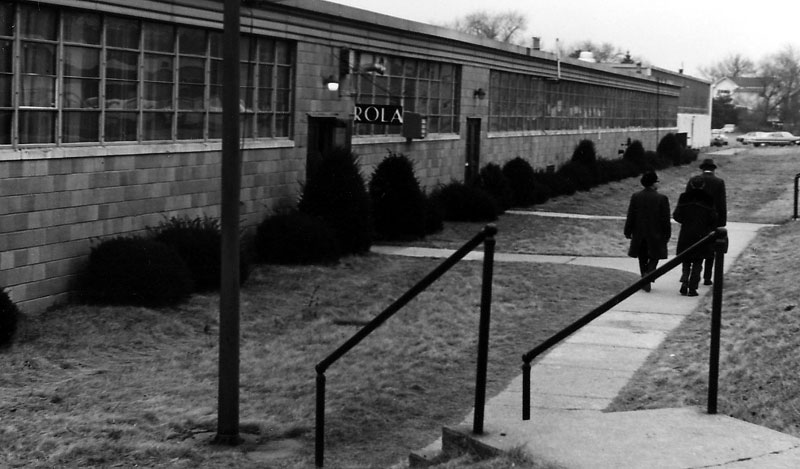
In January, Sidney Corderman and I visit the Rola-Jensen speaker manufacturing facilities in Punxsutawney and Dubois, PA to learn about their production facilities and consider them as a source for drivers.
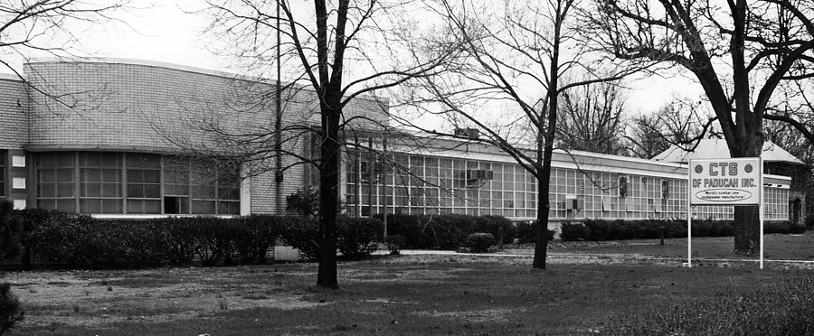
Sidney and I also visit CTS in Paducah, KY as another potential source. They are geared for large production. They even have a very large machine that will stamp out half-inch thick plates for woofer magnet structures. One of the employees said the building shakes when they run that machine. Other smaller machines are used with a progressive die arrangement to stamp out steel baskets.
![]()
Carl Van Gelder Joins McIntosh
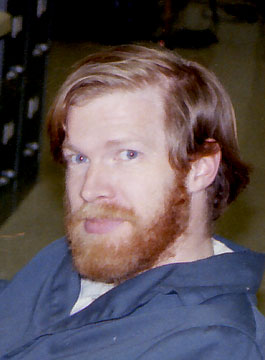 In September, I hire Carl
Van Gelder as a technician to assist in the work on loudspeaker mechanism
designs. He came to me through the Ethan Allen Employment Agency. Although Carl
has a degree in earth sciences, I found he has a natural talent for speaker
mechanisms and eventually he becomes an Acoustic Design Engineer. In 1992 he
receives an important patent for the design of the new McIntosh LD/HP driver
assemblies. With this technology, he is able to reduce driver distortion by a
factor of 10. This improvement is clearly audible, particularly in the voice
range.
In September, I hire Carl
Van Gelder as a technician to assist in the work on loudspeaker mechanism
designs. He came to me through the Ethan Allen Employment Agency. Although Carl
has a degree in earth sciences, I found he has a natural talent for speaker
mechanisms and eventually he becomes an Acoustic Design Engineer. In 1992 he
receives an important patent for the design of the new McIntosh LD/HP driver
assemblies. With this technology, he is able to reduce driver distortion by a
factor of 10. This improvement is clearly audible, particularly in the voice
range.
Over the years Carl and I spend considerable time doing research on acoustics, enclosures, drivers and listening tests. We develop many systems. A few never go into production for one reason or another. We also evaluate many other brands of systems.
 In August I hire Dave Wheaton as an Engineering
Assistant. He has almost completed a degree in electrical engineering at
Cornell. Dave does design work on the systems and makes prototype systems. He
has a talent for conversation and sometimes conducts the seminars for the
visitors in our listening room. That's him on the right portion of the picture.
Dave stays for 5 years and the three of us have a very enjoyable time during
his stay. Then he decides to complete the requirements for his degree. After
graduating, he goes to work for Texas Instruments in Dallas, TX.
In August I hire Dave Wheaton as an Engineering
Assistant. He has almost completed a degree in electrical engineering at
Cornell. Dave does design work on the systems and makes prototype systems. He
has a talent for conversation and sometimes conducts the seminars for the
visitors in our listening room. That's him on the right portion of the picture.
Dave stays for 5 years and the three of us have a very enjoyable time during
his stay. Then he decides to complete the requirements for his degree. After
graduating, he goes to work for Texas Instruments in Dallas, TX.
![]()
 In November of 1973 I am made Director of Acoustic
Research. This is the only business card for key employees that display the Mc
logo. It corresponds to the logo used on the McIntosh speakers. The card
artwork is changed many times over the years. The word Acoustical on my card is
later changed to Acoustic.
In November of 1973 I am made Director of Acoustic
Research. This is the only business card for key employees that display the Mc
logo. It corresponds to the logo used on the McIntosh speakers. The card
artwork is changed many times over the years. The word Acoustical on my card is
later changed to Acoustic.
The ML-10C is added to the line this year and has a 10" woofer. 1-1/2” dome mid and 2-1/4” tweeter. The cabinet style is contemporary, similar to the ML-10C.
We test electrostatic speakers.
Art Janszen had been a consultant for McIntosh for several years. He visits our acoustics lab this time to test his new idea for spiral wrapping the electrodes for his electrostatic tweeter. Earlier versions were constructed using short parallel wires connected together.
Gordon Gow is interested in the Janszen tweeter as a possible high frequency speaker in a McIntosh system. He is also concerned about peak power levels needed to reproduce musical instruments at high frequencies. We set up a microphone at 1 meter and use tone bursts to see how the tweeter will handle short bursts of high frequency power. As the power level re: 8 ohms increases, the acoustic output increases by an equal amount, but at higher power the output begins to decrease. We find that by blowing across the tweeter, the output is temporarily restored. The reduced output is caused by ionized air. The electric stress in the air has exceeded 100V per mil. Ions are produced that in turn discharge the polarizing voltage and cause the output to decrease. By blowing away the ionized air, the polarizing voltage is restored until new ions are formed.
We then compare our dome mid-range at the same sound pressure level and are able to increase the driving power level by many dB above the Janszen while still remaining completely linear.
Gordon learns that the Dayton-Wright electrostatic speaker is enclosed in sulfur hexaflouride gas to eliminate this problem. The thin membrane that encloses the gas is porous, however, and exhibits the osmotic process where the higher density gas molecules migrate through the membrane to the lower density air. The speakers need to be periodically recharged with gas.
As a result of this research and other factors, Gordon decides not to pursue the electrostatic speaker as a viable product.
One day we came in to the building and found the floor covered with water. The office was flooded with about an inch and a half of water. I determine that the water came from a hose that had slipped from the water filter that supplied the humidifier. I call the main plant for help and Mike Stolowyk comes over with a wet vacuum and long handled rubber push blades. Mike was the head of maintenance and by noon, he and his crew have things set in order again.
Plant 5 becomes the storage area for finished XR systems. In the foreground are rolls of Tufflex acoustic material. The lab and wood cutting area are at the far end of the building.
1974
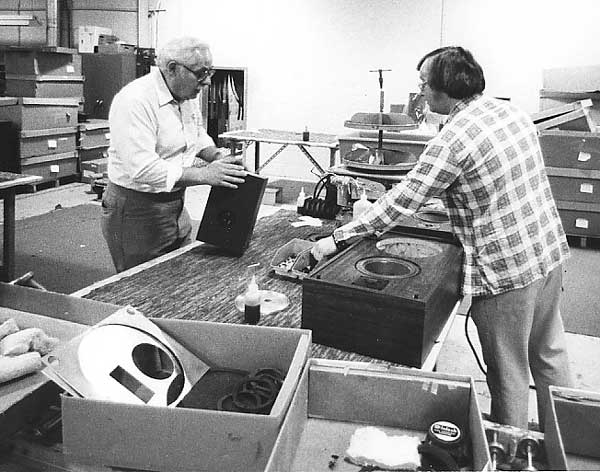
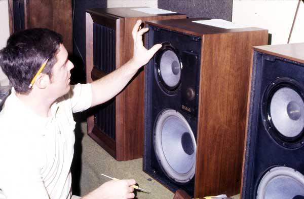
Speaker final assembly begins at plant 5 but in the spring is moved to the new building, plant 7, in Conklin, a few miles south of the main plant. I decide that I did not want to be in charge of both research as well as production. I am dedicated to research and designing more accurate speaker systems. I recognize one of the facets of the Peter Principle is where one gradually rises to their level of incompetence. That is not one of my goals. After discussing this with management, Bob Mayhood (left), who had been manager of the silk screening operation at Plant 2 on Bevier Street until it was moved to the main plant, is assigned to manage speaker production. Bob is shown checking the finish on an XL-1 cabinet. Patrick Sladdish, who works for Bob, is making a final assembly of an XL-10 system. The extra space at plant 5 is then used for warehousing storage items.
About this time we purchase a coil winding machine recommended by George Krenz, a well known voice coil supplier. We also purchase a curing oven and a magnetizer. The magnetizer is a capacitor storage impulse type made by RFL labs in New Jersey.
Being a bike-riding enthusiast, I start to riding my bike to work. It is 7-1/2 miles from my house in Binghamton to plant 5 in Hillcrest. I am able to find a safe route away from the main highways. It takes anywhere from 35 to 45 minutes to get there depending on whether the wind is with me or against me. I ride 2 or 3 times a week. Weather is, of course, a factor. I have rain pants and jacket and ride several times in the rain. I found this very comfortable but take it easy because the wet caliper brakes don't hold very well. I always change my clothes to dress pants, shirt and tie after I get to work. If the temperature is below 45 degrees at home, I don't ride. At 7:30am the temperature in Hillcrest can be 40 or lower and is just too cold for me. I ride spring, summer and fall and find the freedom and scenery very worthwhile. I often take a camera with me.
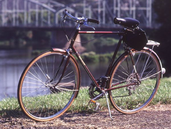
I buy a Raleigh Sprite 10 speed bike to replace the 3-speed Raleigh I had used at college. I assemble a new gear cluster with higher gear ratios for hill climbing and strong wind. I also use Zeus non-pneumatic hollow urethane tires that just don't get flats. They are said to last for over 3500 miles. The Sprite is a touring bike and not a super light weight racing bike. I continue to ride even after we moved next to the main plant in 1979. In the background is the Washington Street Bridge, It is closed to cars and trucks but is open for walking and bikes. This is how I cross the Susquehanna River on the way to Plant 5.
Instead of staying in the building during lunch time, I decide to get outside. There is a large field behind the building. I can walk across this to a wooded area and through there to the Chenango River. I find many interesting plants including troutlilies, bloodroots and ferns. I always have a camera with me on these excursions and take many pictures. In the winter, the river ice makes unusual patterns. These noontime adventures at plant 5 are now available to view.
1975
About this time the Stereo Technology
(Stereotech) line is introduced. To complement the
first Stereotech receiver, we design four speaker systems, ST 1, 2, 3, and 4.
McIntosh assembles the systems and the crossovers. CTS, Rola-Jensen and
Peerless supply the drivers. The cabinets are to be lower cost and are
purchased with a walnut vinyl laminate. Unfortunately the increase in material
costs force the Stereotech program to end in 1976.
![]()
We are scheduled to come out with revised versions of the ML systems, the ML-1D, ML-2D, ML-2N, ML-4D, ML-4N and ML-10D. The systems are to have the same cabinets. Printed circuit crossover boards are used in place of the hand-wired boards. Fuses are added to protect the crossovers and drivers from being overdriven by clipping amplifiers. Indicator lights are also added. Each system has a main fuse that is connected to the crossover network input. If the system is driven near the maximum power handling, a yellow warning light will be seen. If the main fuse blows, and the system continued to be driven, the yellow light will still be seen, but there will be no sound. A smaller high frequency fuse is used to protect the upper mid-range and tweeters. If the tweeter fuse blows, and the system continues to be driven, a red light will be seen but no highs will be heard.
The lights and fuses are mounted on two small plates on the front board of the ML-1D. The yellow light and main fuse are on the left plate and the tweeter fuse and red light are on the right plate. The lights can be seen between the slats in the grille and through the grille cloth. In the ML-2's and 4's, the fuses are on the front board behind the grilles. The lights are mounted under the base of the cabinet and clear plastic rods are used to bring the light to the front of the base.
Gordon Gow decides it was time to revise the style of the cabinets, however, and the D's and N's are never produced. As the decision is made close to the scheduled production date, some ML-1 and ML-10 cabinets already have cutouts for the fuse plates. These are covered with solid plates and sold as ML-10C systems. Some ML-10C systems have printed circuit boards with space ready for parts to be made as ML-10D’s. The lettering on some cartons said ML-1D and ML-10D. See my ML-10D page for a detailed description and pictures of this system. The Polygon Systems are developed about this time. Although they are very unusual in design they never go into production.
![]()
About this time I met Uolevi Lahti. Gordon introduced him as a McIntosh dealer in Ann Arbor Michigan. There is no known relationship to Christine Lahti, the movie star. Back in the 1950s, Uolevi had a classical record store in downtown Ann Arbor. He also designed and built his own loudspeaker systems that he sold under his own name. However, by the 1960s he expanded his store to include Hi-Fi equipment and had line of several different loudspeaker systems. He incorporated his business in 1964. According to one source, he never acquired any national distribution and seemed to be content with local sales as a one-man operation.
I had several enjoyable discussions with him at the lab and at the Gaslight restaurant in New York City. He talked about his designs and was interested in my opinion of his systems. They were initially 2-way bookshelf models but later models included a few unconventional designs like the spherical system. The tweeter is at the top of the ball facing upward. It has a circular part about 3 inches across on the top that can be raised up, tilted and rotated in different directions to direct the high frequencies. The woofer faces downward.
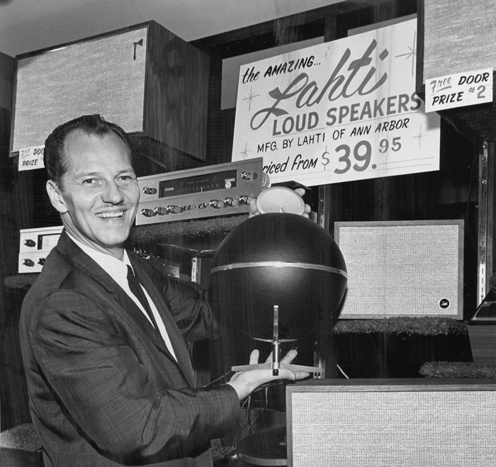
Photo is dated Nov 21, 1965
He also had some PA and commercial speakers. One of his ideas was to incorporate pink noise through the air conditioning systems to mask out office noise. Frankly, after Emory Cook mentioned that he found himself tending to fall to sleep while monitoring bands of pink and white noise for his test records, I think it might have the same effect on the office workers.
His company closed down in1978 and dissolved in 1980. He moved to La Belle, FL that is just to the east of Cape Coral and Ft. Myers. He may have continued to manufacture speakers there for the industrial and communications market. Soon after I left McIntosh in 1990, I had called him to let him know I was now living in Florida as well. Unfortunately, his wife informed me that he had recently passed away. At least I can add this tribute to him even at this late date. I remember he was enthusiastic about his recent acquisition of a pocket real time analyzer that he showed to me.
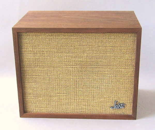
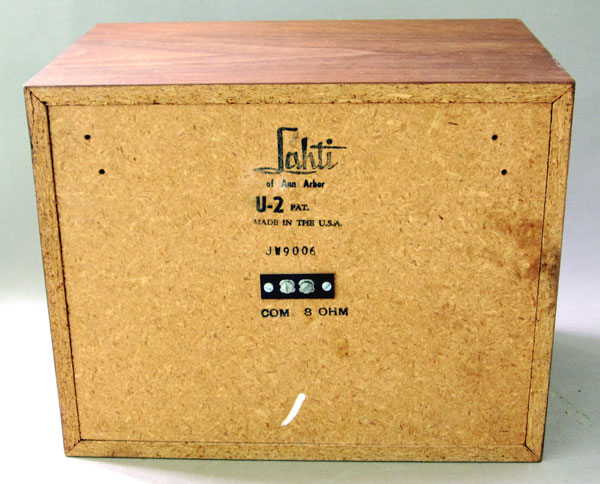
Lahti U-2 Speaker System
This is a 2-way system. Because of the logo orientation and lettering on the back, the system was apparently designed to be used on its side. The dimensions are Height 9-1/4”, Width 11-3/4” and depth 7-3/4”. It weighs about 10-3/4 lbs.
|
|
|

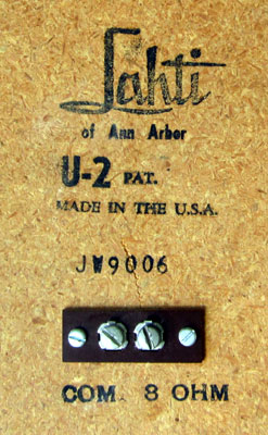
The logo is cast metal. On the back of the enclosure is the amplifier
connection.. A serial number is also stamped on the back. The pair that I
bought has serial numbers JW9005 and JW9006. The system is 8-ohms. No easy
access is provided to access the drivers for repairs. It seems that once the
box was put together, it was not intended to be opened. The grille cloth seems
to be glued in place and does not pull to the side to be removed. The solution
may be to destroy the grille but even then the drivers may not be easily
removed. The four small holes in the back may have been only for a wall
mounting bracket and not for some kind of tool to pull the back off. Anyone for
a Chinese box puzzle?
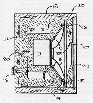
The design for the woofer is similar to his first patent in 1964 titled Loudspeaker. The patent describes loudspeaker enclosures, and more specifically high fidelity loudspeaker enclosures having extremely low frequency response, which is attainable by means of a very small physical structure.
 Uolevi received several patents on his ideas:
US patent 3,135,349 Loudspeaker June 2, 1964
US patent 3,435,910 Semispherical Loudspeaker April 1, 1969
US patent 3,500,953 Loudspeaker System March 17, 1970
US patent 3,812,301 Spherical Loudspeaker May 24, 1974
US patent 4,485,275 Inverted Horn Loudspeaker November 27, 1984.
At the left is a diagram from his 1964 patent, Loudspeaker. It is similar to the driver arrangement in the U-2 system. Here, the driver faces into what appears to be an inverted cone with an opening in the center. The driver and cone are located in the enclosure with a common center line. This design appears to be similar in a way to the old R-J (Robbins-Joseph) type of enclosure that I have seen with an S-shaped port in front of the driver. However, in the Lahti system, the driver is not mounted on a separate board spaced back from the cabinet front board. The front of the driver compartment of the U-2 is sealed from the back compartment.
The front cabinet wall is cut to provide an inverted exponential horn. The front load for the driver is the tapered shape with a small opening to the outside. Sharp edges at the hole further increase air turbulence that behaves like an acoustic resistance. In a Helmholtz resonator like in a soda bottle, the mass of air in the neck of the bottle resonates with the compliance of air in the bottle body. But Lahti has eliminated the neck and there is no Helmholtz resonance produced. There is no tuning needed to match the driver characteristics. This is confirmed by a single impedance peak at low frequencies like that found in a sealed system. In the U-2 system, the peak is at 150Hz and no other peaks out to 20kHz. However, the increased air mass in front of the cone effectively loads the cone and results in a lower system resonant frequency. Although it can extend the low frequency response, it is at the expense of lower system efficiency. It is the same as increasing the mass of the driver moving parts. The turbulence can serve to lower the Q of the system and “boomy” sound particularly when used with high Q drivers. In effect, the system begins to accomplish a similar performance to the Acoustic Research woofer having a heavy moving mass for low resonance in a small box and a low Q driver.
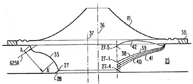
In the 1984 patent, he has replaced the shaped front board with an inverted speaker cone complete with surround and the coil hole is in the center (36). It is skewed to one side of the driver center (37), perhaps to reduce high frequencies when a separate tweeter is used. However, when using a full-range driver, the center area of the cone should be open to the center of the cabinet hole in order to effectively radiate the high frequencies.
|
About This Site |
||
|
|
More text and pictures about McIntosh will be added as my research continues. Any comments, corrections, or additions are welcome. |
|
|
|
Created
by Roger Russell |
|