Speaker Wire
A History
by Roger Russell
This material is copyrighted
No portion of this site may be reproduced in whole or in part
without written permission of the author.
![]()
![]()
WIREBUSTERS
“It's
easier to fool people than to convince them that they have been fooled.”
----Mark Twain
For many years, wires that were used to connect speaker systems were often zip or line cord. The longer the run was, the heavier the wire that was used. There were no special speaker wires--just plain old copper wire--solid or stranded. The emergence of high tech speaker wire has raised some fundamental questions about the benefits of these new and sometimes extremely expensive wires.
Resistance in the speaker circuit is the key factor that determines loudspeaker performance. The loudspeaker circuit includes the connecting wire between the amplifier terminals and the speaker terminals, the amplifier internal impedance and the impedance of the speaker system. There's also contact resistance at the connecting terminals of the amplifier and speaker system. The contact resistance of clean connectors and the internal impedance of good quality amplifiers is normally small. The controlling factors that remain are the speaker system impedance and the speaker wire resistance.
The DC resistance of a typical 8-ohm speaker system is about 7 ohms. This resistance is due to the wire in the woofer voice coil. It may be a total shock to some people to know that a typical 8-ohm four layer woofer voice coil contains about 120 feet of number 28 solid copper wire. This wire is all in the circuit with the speaker system hookup wire. It's also much longer than a normal run of hookup wire from the amplifier to the speaker. Even a mid range speaker can have about 30 feet of number 33 solid copper wire and a tweeter can have 20 feet of number 35 solid copper wire.
Speaker and Amplifier Connectors
The connection between the power amplifier output terminals and speaker input terminals is almost always a pressure device of some sort. It's unfortunate that these important connections are determined by to how tight you can turn a binding post or screwdriver or by the pressure of a spring which holds the speaker wire against the metal of the terminal. The metals that are forced against each other are often different. They might be brass or steel but plated with other metals. The wire could be copper or silver and perhaps coated with solder containing tin. They expand and contract differently with temperature. They can also become oxidized over time and the connection can become bad to the point where the resistance is significant compared to the resistance in the rest of the circuit. Dissimilar metals can also promote corrosion with action like a battery when they are in a humid environment. This eventually causes not only higher resistance but also clearly audible distortion as if a diode were inserted in series with the speaker and amplifier.
Suppose you have a system with adequately heavy speaker wire but the connections have gone bad over time. Simply removing and cleaning the wires and terminals and reconnecting them can make an audible difference. Incidentally, this is what can happen if the old wire is replaced with a new "miracle" speaker wire. By disturbing the terminals this can "accidentally" improve the contacts when the new wire with its clean surface is installed. A difference can be heard but not because of the new wire. The same change can be heard by simply cleaning the old wire/terminal contacts and reconnecting them.
Ah, you say gold plating takes care of all that. That isn't always true, particularly if the wire is tinned with solder, which is at least 50% tin, and the connecting post is gold plated. Here's what J. J. Whitley, Research Associate at AMP Incorporated (a well-known connector manufacturer) has to say about mating tin-plated contacts with gold. "In most cases, lubricated tin contacts can be mated with gold-plated contacts. This combination works as long as the conditions of contact force and stability for tin contacts are met."
"There is one major exception--where the service conditions involve wet or humid environments. Under these conditions, the gold-tin bimetallic junction is subject to galvanic corrosion. Generous application of protective lubrication is one way to alleviate this problem."
It would seem logical that instead of connecting the output wires inside the power amplifier to the output terminals, the wires should be wrapped and soldered directly to the speaker wires. Then, in turn, the other end of the speaker wires should be wrapped and soldered directly to the speakers, or crossover network. This is not practical, of course, unless the amplifier and speaker are integrated in the same cabinet.
![]()
What is damping factor and how important is it? Here are two articles written about damping factor. Although they were written some time ago, they are just as valid today as they were back then.
“Damping, Damping Factor, and Damn Nonsense” by Floyd Toole, Audio Scene Canada, February 1975.
“The Damping Factor Debate” by George Augspurger, Electronics World, January 1967.
![]()
In the early speaker manuals, starting with the XR5, I included a chart for estimating the maximum wire lengths for various sizes of copper wire needed for 4 and 8 ohm loads. I have expanded it on this page to include 2 and 6 ohm loads as well. It was based on the resistance of the speaker wire not exceeding 5% of the rated impedance of the system. The wire length is for TWO-CONDUCTOR wire. This includes one wire out to the speaker and one wire back again.
Wire is specified by gauge numbers. A smaller number indicates a larger diameter of wire and consequently a lower resistance. Stranded wire is composed of several smaller conductors. The total cross sectional area of all of the smaller conductors determines the effective wire size of the stranded wire and it will have lower resistance than only one of the strands. This is analogous to resistors in parallel.
Maximum Wire Lengths For TWO CONDUCTOR Copper Wire
|
Wire Size |
2 ohm load |
4 ohm load |
6 ohm load |
8 ohm load |
|
22 AWG |
3 feet max |
6 feet max |
9 feet max |
12 feet max |
|
20 AWG |
5 feet max |
10 feet max |
15 feet max |
20 feet max |
|
18 AWG |
8 feet max |
16 feet max |
24 feet max |
32 feet max |
|
16 AWG |
12 feet max |
24 feet max |
36 feet max |
48 feet max |
|
14 AWG |
20 feet max |
40 feet max |
60 feet** |
80 feet** |
|
12 AWG |
30 feet max |
60 feet** |
90 feet** |
120 feet** |
|
10 AWG |
50 feet max |
100 feet** |
150 feet** |
200 feet** |
For example: you can use#18 wire for a 25 foot run to a nominal 8 ohm speaker, but if the run is increased to 35 feet, #16 wire must be used. (**) 50 feet is the maximum recommended length for normal line cord or Romex solid copper wire. This length is more than adequate for most installations. An explanation is further down on this page titled "What about Wires Longer Than 50 Feet?".
A wire resistance of less than 5% of the nominal speaker impedance is chosen to work well with almost all speaker systems and can be considered conservative. Even a resistance of less than 10% of the nominal value could be used with some speakers and would not be audible. A further explanation can be found in a later section.
![]()
A nominal impedance value is not always accurate because most systems vary with frequency. A speaker that is rated by the manufacturer as 4 ohms may not be 4 ohms at all frequencies. It can wander above or below this value and is unique for different systems.
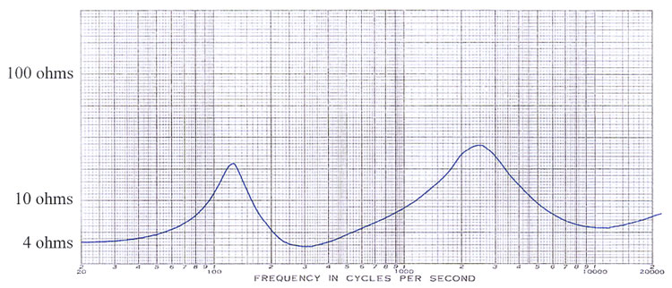
The above impedance curve is for a small 2-way speaker system that is rated at 4 ohms. The lowest impedance for this system is 4.7 ohms in the area of 20Hz, 4.0 ohms at 300Hz and 5.9 ohms at 11kHz. The maximum impedance is 20 ohms at 125Hz and 28 ohms at 2500Hz. The rated impedance is normally the lowest value in the curve and in this example; the system is rated correctly at 4 ohms. When the impedance rises higher than the nominal value, this is not a problem for a power amplifier. However, some systems may deviate significantly below the rated impedance and this could be a problem for a power amplifier, particularly where matching output transformers are concerned.
Some amplifiers with multiple output impedance taps can safely drive 8 ohm nominal systems having impedance as low as 6.4 ohms without requiring connection to the 4-ohm tap. Direct-coupled amplifiers, of course, do not have this limitation as long as the higher power delivered as a result of the lower impedance does not cause the amplifier to be overdriven. If you have doubts about your system impedance, it's best to contact the manufacturer concerning the lowest impedance of the system that you plan to use and select a connecting wire based on the lowest impedance value.
![]()
What happens when the resistance gets too high? First, there is power lost in the wire and the speaker will not play as loud. More important, as the resistance in series with the speaker increases, it makes the amplifier look more like a current source. This means the speaker frequency response will tend to follow the rise and fall of its impedance curve. The greater the impedance variation, the more noticeable the response changes will be. If the speaker has constant impedance versus frequency, the only change will be reduced output.
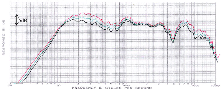
Response in the above set of curves is for the same small 2-way 4-ohm speaker. The microphone position is only a few inches from the system but that is not important for this example. Here, we are interested in response differences for different series resistance for the same microphone position and not for speaker response at different microphone positions.
The red (upper) curve is without any added series resistance. The green (middle) curve is with one ohm added in series with the speaker and the black (lower) curve is with 2 ohms in series. You can see there is an overall loss in output but it is not the same at all frequencies. For the green (middle) curve in the area of 125 and 2500Hz, where the impedance is high, there is only about 1/2dB of loss in output whereas at the area of lowest impedance, at 300 and 10 kHz, the loss is about 2dB. The larger 2 ohm resistance shows even greater changes.
The resistances used in this example are much larger than the recommended wire resistance of 0.2 ohms but they do show how impedance variations can influence response. Response changes this large can be easily heard in an A-B listening test.
Part 1: Speaker Impedance and Wire Resistance
Part 2: Amplifier stability and Wire Capacitance
Speaker Impedance and Wire Resistance
Knowledge of the speaker impedance over the entire frequency range is a very important factor in an A-B listening test. This is shown by the response curves in the above section. In some listening tests, this can cause a difference in sound that could result in false conclusions because the wire is not heavy enough. Suppose a speaker is used that has an advertised impedance of 8-ohms but the impedance actually drops to 4 or 5 ohms at one or several frequencies. Suppose further that wire A used in the test is heavy enough for an 8-ohm speaker but not for a 4-ohm speaker. When making a comparison test with a heavier wire B, differences can then be heard. Although the resistance of wire A may be correct for the advertised impedance, it may be too high if the speaker impedance goes lower than that. It has nothing to do with the kind of wire, only that the resistance of one wire may be too high for that particular speaker used for the listening test.
This lack of understanding for the impedance behavior of a speaker used for a listening test may explain listening differences that people can truly hear. One wire can truly appear to sound different than the other but for the wrong reasons. A speaker that has a constant impedance at all frequencies (most speakers do not) will only show a difference in listening level and not alter the response when the wire size is too small for A or B. Of course, the listening levels will be different unless they are compensated for in advance. Otherwise, the louder sounding one will likely be chosen. To avoid these difficulties, whether the speaker has constant impedance or varies, the two wires to be compared should have the same total resistance and that could mean different lengths would be needed to make the resistances equal.
Otherwise, under these adverse conditions of different resistance, a person can select one wire consistently. It may be easy to hear differences in the frequency range or ranges where the speaker being used has impedance dips that are below the rated value of the speaker. In some marginal cases it may even be possible, depending on the bandwidth of the speaker impedance dips, to hear differences that go near but not below the rated impedance. However it is a false conclusion that the wire selected is because of a unique wire construction or other advertised features. Only the difference in wire resistance is being heard due to the speaker being used in the listening test.
Of course, a different speaker will most likely have a different impedance curve depending on the crossover design and whether it is a single wide-range driver, two-way, three-way, etc. system. In that case an impedance dip or dips can be in a different frequency range and have a different bandwidth. A listening test will then reveal yet a new set of sonic differences. Again, resistance is the key.
Bear in mind that if both wires in the test are much heavier than needed for the particular speaker that is used and the speaker impedance is fairly constant, small wire resistance differences may have little influence in the test.
Amplifier Stability and Amplifier Performance
Several speaker wire manufacturers make wire that has high capacitance yet almost none of them publish exactly what the capacitance actually is. Capacitance is of concern not so much that it could cause a possible high frequency rolloff but that it can affect the amplifier feedback and cause the leading edge of transients to overshoot. This in turn can make an audible difference in the system sound. It can make the sound brighter, which some audiophiles mistake as greater detail.
 Here are some examples using two different amplifiers
and two different speaker wires. Although both amplifiers are made by the same
manufacturer, they are different models and were designed at different times.
One wire in the test is ordinary #12 wire having multiple strands. It looks
like heavy line cord. It tests at 18pf per foot and sells for about 30 cents
per foot. The second wire is an expensive speaker wire having a higher
capacitance of 280pf per foot and sells for about $28.00 per foot. I will refer
to this as high-cap wire. The resistance of both wires is very low.
Here are some examples using two different amplifiers
and two different speaker wires. Although both amplifiers are made by the same
manufacturer, they are different models and were designed at different times.
One wire in the test is ordinary #12 wire having multiple strands. It looks
like heavy line cord. It tests at 18pf per foot and sells for about 30 cents
per foot. The second wire is an expensive speaker wire having a higher
capacitance of 280pf per foot and sells for about $28.00 per foot. I will refer
to this as high-cap wire. The resistance of both wires is very low.
The high cap wire length is 18 feet giving a total capacity of 5040pf.
The #12 wire length is 12 feet giving a total capacity of 216pf.
To double check, I later ran 25 feet of #12 wire having a total capacity of 450pf that showed results close to the 12 foot wire.
For what it is worth, the speaker terminals measure 6pf and dual banana plugs measure 4.7pf. Both contribute an insignificant capacitance compared to speaker wire..
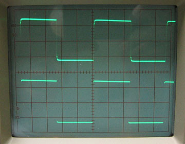
Amplifier A is a stereo amplifier with one channel driven. Amplifier B is a single channel amplifier.
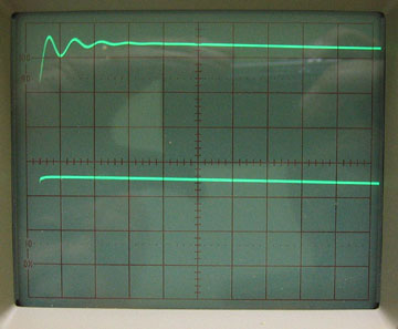
I have used a 10kHz square wave as a test signal. The photo at the left shows the square wave test with amplifier A. I have used a dual trace oscilloscope to monitor the power amplifier output as well as the square wave generator output that is connected to the power amplifier input. The lower trace in the photo is always the generator output that runs to the power amplifier. The upper trace is the power amplifier output with an 8-ohm resistor termination at the end of the wire but the details of the leading edge are hard to see. However, in all of the following photos, the oscilloscope sweep is expanded to better show the leading edge.
Amplifier A with a resistor connected as a load
|
Through#12 Line Cord |
Through High-Cap Wire |
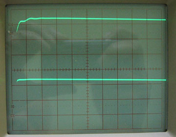
Amplifier A shows no overshoot with the line cord but does show overshoot when the high-cap wire is used.
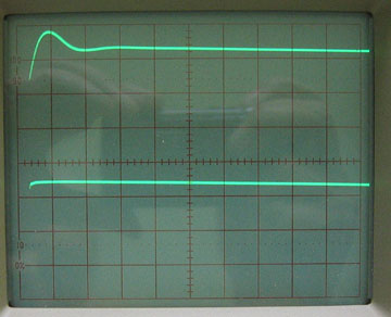
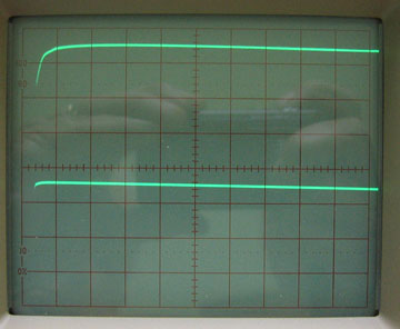
Amplifier B with a resistor connected as a load
|
Through #12 Line Cord |
Through High-Cap Wire |
Amplifier B remains unchanged with no overshoot for either kind of wire
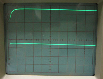
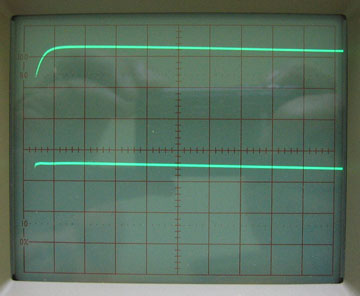
Amplifier A VS Amplifier B with a speaker connected through high-cap wire.
|
Amplifier A |
Amplifier B |
With a loudspeaker system connected as a load for amplifier A, the waveform leading edge shows further deformation compared to the resistor load. In fact, it indicates a tendency towards oscillation. Either channel of stereo amplifier A shows the same result. Meanwhile, amplifier B still remains essentially unchanged with no tendency to overshoot.
Conclusions
The degree of influence when using high capacitance wire depends on three factors.
1. The total capacitance of the wire used (capacitance per foot times the number of feet).
2. The complex impedance of the speaker being used.
3. The stability of the amplifier being used to drive the speaker.
When there is an audible difference in speaker wire due to wire capacitance, it can be interpreted as an improvement when one wire appears to have more clarity but is actually altering the sound and departing from accuracy. Perhaps this change in sound then paves the way to sell more wire. Further, perhaps the wire companies already know this and what will sell. If the speaker wire companies had not introduced wire having high capacitance, either out of ignorance or by intention, then there would have been no controversy like this and ordinary low resistance wire, which incidentally has very low capacitance, would have remained king from the beginning.
Twelve gauge Romex has a capacity of only 15pf/foot. Fifty feet has a total capacitance of only 750 pf, which is the same as 000750 microfarads (mfd).
Twelve gauge line cord has a capacitance of only 18 pf/foot and 50 feet has a total capacitance of only 900 pf, which is the same as .000900 microfarads (mfd).
Although some expensive wires can have low resistance, several have a high capacitance of 100 to 300 picofarads (pf) per foot. These can introduce a significant amount of capacitive load, particularly for longer lengths. For a 50 foot length, this adds up to 5000 to 15,000 pf, which is the same as .005 to .015 microfarads (mfd).
Unfortunately, in addition to sounding different with a small amount of overshoot, a few unstable or borderline amplifiers can even go into oscillation. Low power oscillation, even if ultrasonic, will further affect the listening performance of a system and could lead to an apparent mysterious burnout of a tweeter. Oscillation at full power could cause an amplifier and/or speaker system to burn out.
However, there is another side to the story and not all amplifiers show instability or overshoot when burdened with high capacitance wire. For instance, when further tests were made with amplifier B using a capacitor to simulate a capacitive load, values of capacitance of up to 20,000pf (.02mfd) showed no change in performance. A well-designed amplifier will not have a problem with any of the high capacitance wires found to date.
Cobra Cable
Cobra Cable was sold by Polk Audio many years ago but has long since been discontinued. The idea was to reduce the cable inductance but in doing so, increased cable capacitance. Cobra wire had many separate strands that were individually insulated with a thin material. These all ran in parallel and comprised one conductor. The insulation was colored black for one group. The other conductor was a similar group of strands but the insulation was colored red. The strands of each color were interwoven with each other and formed a braided but cross-coupled two-conductor cable. Of course, the strands being very close to each other and with thin insulation, resulted in an unusually high cable capacitance. The high capacitance of Cobra Cable was the same as connecting an unusually high value capacitor directly across the amplifier terminals. Reports indicated that a resistor-inductor termination could be added to prevent oscillation when this wire was used with unstable amplifier designs that cause transient overshoot and even amplifier oscillation.
Related Information
An article titled Sineward Distortion by John W. Campbell, Jr. suggests that the ear is a wave-form analyzer and not a harmonic analyzer. It is part of our hearing mechanism that has evolved for our survival over millions of years. Although sine wave analysis is interesting, it is not how we hear. Our ears hear more like an oscilloscope. For many years, sine waves have been used to measure response as well as harmonic and inter-modulation distortion. They have been a convenient way of specifying amplifier performance and can verify that the amplifier is an excellent sine wave amplifier. However, there is more to consider that may also be relevant. Will the amplifier reproduce any other waveform and remain stable?
![]()
What if you use wire heavier than the minimum size recommended in the table? There is no audible improvement but there can be a considerable increase in cost. On the other hand, it would be a conservative choice, particularly for in-the-wall installation where you might someday be using lower impedance speakers and would need to replace the existing wire with heavier wire. Solid copper house wiring is sometimes less expensive than multi-stranded wire. Heavier solid wire is harder to work with, though, and that may require special connectors to fit the amplifier and speaker terminals.
![]()
What about “oxygen free” wire?
Oxygen-free copper (OFC) or Oxygen-free high thermal conductivity (OFHC) copper generally refer to a group of wrought high conductivity copper alloys that have been electrolytically refined to reduce the level of oxygen to .001% or below. Perhaps, it should be more accurately called oxygen reduced copper.
C11000 is the most common copper. It is universal for electrical applications. Electrolytic-Tough-Pitch (ETP) has a minimum conductivity rating of 100% IACS and is required to be 99.9% pure. It has 0.02% to 0.04% oxygen content (typical). Most C11000 sold today will meet or exceed the 101% IACS specification. For the purposes of purity percentage, silver (Ag) content is counted as copper (Cu).
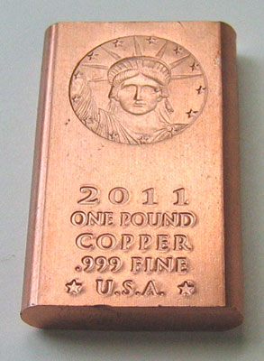
Here is a one pound ingot of .999 (99.9%) fine copper.
Once copper has been concentrated, it can be turned into pure cathode copper in
two different ways:
Leaching & electrowinning or smelting and electrolytic refining.
C 10200 is known as Oxygen-Free (OF). Its conductivity rating is no better than the more common C11000 grade mentioned above. However, it has a 0.001% oxygen content, 99.95% purity and minimum 100% IACS conductivity. For the purposes of purity percentage, silver (Ag) content is counted as copper (Cu).
C10100 is known as Oxygen-Free Electronic (OFE). This is a 99.99% pure copper with 0.0005% oxygen content. It achieves a minimum 101% IACS conductivity rating. Silver (Ag) here is considered an impurity in the OFE chemical specification. This copper is finished to a final form in a carefully regulated, oxygen-free environment. It is also the most expensive of the three grades.
Many owners of high-end audio and video equipment value “oxygen free” copper. Behind this demand is the belief that it will have enhanced conductivity or other electrical properties that are significantly advantageous to audio signal transmission. However, as indicated above, most C11000 common copper sold today meets or exceeds the 101% IACS conductivity and overlaps C10200 “oxygen free” that has a minimum of 100% IACS conductivity. In practice, there is no significant difference in conductivity between all three of the grades as far as audio use is concerned. It can be considered to be ordinary copper wire as far as the recommended lengths of copper wire in the table. However, for industrial use, C10100 OFE copper is valued for purity and used for such applications as plasma deposition, semiconductor manufacture and particle accelerators.
![]()
What about Silver Wire and Conductivity?
Conductivity is a measure of the ability of a substance to conduct electricity. When the resistance is low, the conductivity is high. Copper is the standard by which electrical materials are rated and conductivity ratings are expressed as a relative measurement to copper. These ratings will frequently be expressed such as "28 IACS". IACS is the abbreviation for International Annealed Copper Standard and the number preceding "IACS" is the percentage of conductivity a material has relative to copper, which is considered to be 100% conductive. This does not, of course, mean that copper has no resistance, but rather that it is the standard by which other materials are compared. The higher the % IACS, the more conductive the material is. This standard is based on an annealed copper wire having a density of 8.89 g/cm3, 1 meter long, weighing 1 gram, with a resistance of 0.15328 ohms. This standard is assigned the value 100 at 20°C (68°F). Here are some examples of conductivity values for a few common materials.
|
Material ICAS% Conductivity |
|
|
Silver |
105% |
|
Copper |
100% |
|
Gold |
70% |
|
Aluminum |
61% |
|
Brass |
28% |
|
Zinc |
27% |
|
Nickel |
22% |
|
Iron |
17% |
|
Tin |
15% |
|
Phosphor Bronze |
15% |
|
Lead |
7% |
|
Nickel Aluminum Bronze |
7% |
|
Steel |
3 to 15% |
The percentages of tin, aluminum, nickel, zinc and phosphorus that make up alloys such as brasses and bronzes are relatively small but they degrade the electrical conductivity of the resulting alloy much more than their compositional percentage would indicate. However, there are instances where the superior tensile and machining characteristics like brass make it a better choice than copper as long as the sectional areas are increased proportionately to achieve the same electrical conductivity that a copper part would have for the same application. Size for size, however, copper is exceeded only by silver among the materials commonly used for electrical applications. Silver is more expensive but there is no listening difference, provided the resistance is low enough.
![]()
Oh my. What next? Now it looks like copper clad aluminum (CCA) speaker wire is next. The conductivity of aluminum is less than copper by about 61%. To get the same resistance as copper, a thicker aluminum wire is needed. A thin layer of copper is on the outside and aluminum is on the inside. This is like having two resistors in parallel. The equivalent resistance compared to plain copper wire depends on the proportion of the smaller cross sectional area of the copper and the larger cross section of the aluminum.
Why is this being done? Likely it is because the price of copper is still increasing. Remember that in 1982 the US Mint changed the composition of the penny. Even then, the value copper in a penny was rising until it was worth more than one cent. As a result, the penny was changed from 95% copper and 5% zinc to 97.5% zinc and 2.5% copper. Zinc is a lot cheaper
Aluminum wire is nothing new for the power companies. Surprising as it might be, aluminum conductors reinforced with steel (known as ACSR) are primarily used for medium and high voltage overhead lines and may also be used for some overhead services to individual customers. Aluminum conductors are used as it has the advantage of lower resistivity per weight than copper, as well as being cheaper.
There was a problem with aluminum house wiring prior to 1972 because of improper installation techniques resulting in poor contact with other devices. Today, copper wire is still the preferred choice in homes.
How do you know what you are buying these days? Unless a speaker wire company tells you are buying copper clad aluminum wire and what the equivalent resistance compared to plain copper is, then it is buyer beware.
Is there any listening difference with copper clad wire compared to ordinary copper wire, resistance being equal—no. However, it could be an opportunity to make some ridiculous claims about listening improvements.
![]()
What about Wires Longer Than 50 Feet?
Besides losses due to cable resistance, longer cables begin to exhibit a significant reactive component of capacitance and inductance regardless of the wire size. Measurements I have made show that response in the 10 kHz to 20 kHz region is affected by a small amount. Then why are differences in extended wire lengths not heard? There are at least two reasons. Both are related to our hearing ability.
An article was published in Audio, July 1994 titled "Speaker cables: Measurements Vs Psycho-acoustic data" by Edgar Villchur. The psycho-acoustic data shows that for pure tones at 16kHz the smallest average detectable difference in level is 3.05 dB. He also indicates: "It can be predicted that at a given level the just noticeable difference will be increased by a significantly greater amount by the masking effect of musical sound below 10 kHz." (See note 1). The findings were based on individuals 20 to 24 years old that had normal hearing to 20 kHz (See note 2). This is what might be called the best of conditions for hearing differences.
However, as we age, our sensitivity to high frequencies decreases dramatically. The chart is from Modern Sound Reproduction by Harry F. Olson. It shows the average hearing loss Vs age for men and women at frequencies from 250 Hz to 8000 Hz. This means that for a man at age 35, sensitivity is down about 11 dB at 8000 Hz. For a woman at that age, sensitivity is down only about 5 dB. We can infer that sensitivity is down a whole lot more at 20kHz.
So for these two reasons this measurable high frequency wire loss in the 10 to 20kHz region is not audible for moderately long wires like 50 feet. Longer runs may still not be audible for some people, provided the wire resistance is kept low enough.
(Note 1) An article was published in the Journal of the Audio Engineering Society by Lipshitz and Vanderkooy titled "The Great Debate: Subjective Evaluation" Volume 29, No. 7/8 July/August. They estimated that when level differences occurred over a wide band, they were detectable down to 0.2 dB. However, in a phone conversation with Villchur, Lipshitz agreed this figure is not applicable to speaker cables where the level differences are all in the highest audio octave.
(Note 2) Villchur gives a reference of Florentine, Buns and Mason "Level Discrimination As a Function of Level for Tones from 0.25 to 16kHz" Journal of the Acoustical Society of America, Vol. 81, No. 5 (May 1987)
Gordon Gow's Speaker Wire Listening Test
 I have read several magazine articles and papers
expressing the findings and opinions about the various kinds of speaker wire.
Some engineers have applied their expertise to make measurements to prove
conclusively that there ARE differences between wires. A few authors have
devoted their entire paper to the measurements and never mention whether they
have actually made any listening tests or if they could hear any difference.
Despite all the measurements and opinions, the final test is whether you can
hear any difference or not. Obviously, this must be done under controlled
conditions where you don't know which wire is connected and there is no delay
in switching.
I have read several magazine articles and papers
expressing the findings and opinions about the various kinds of speaker wire.
Some engineers have applied their expertise to make measurements to prove
conclusively that there ARE differences between wires. A few authors have
devoted their entire paper to the measurements and never mention whether they
have actually made any listening tests or if they could hear any difference.
Despite all the measurements and opinions, the final test is whether you can
hear any difference or not. Obviously, this must be done under controlled
conditions where you don't know which wire is connected and there is no delay
in switching.
In the early 1980's, special speaker wires
were beginning to appear on the market. Some of the claims were totally
unbelievable and had prices to match. Realizing that wire resistance was the
critical factor in speaker wire, Gordon Gow,
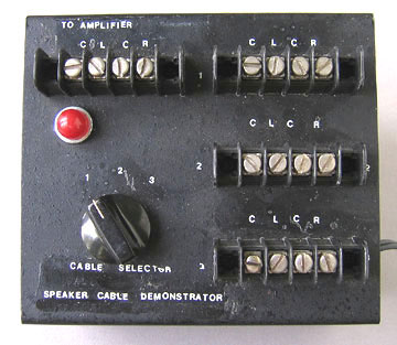
President of McIntosh Laboratory, used a speaker cable demonstration to show
there was no listening difference between these wires and plain line cord. He
delivered his presentation about the truth in speaker wire using a reel of
Monster cable to stand on. Fifty-foot lengths of wire were used in the
comparison. The setup consisted of a master control relay box and two slave
relay boxes. A three-position switch was used to select one of three different
speaker wires of equal length. One was line cord. The other two wires were from
popular manufacturers. 8-ohm speakers were selected to be used 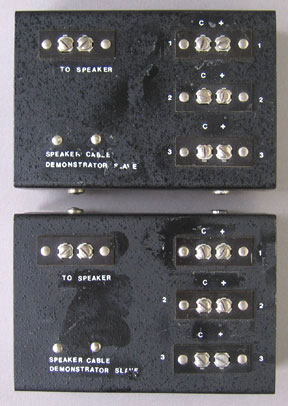 in the test. The two other brand name wires were
heavier than the line cord.
in the test. The two other brand name wires were
heavier than the line cord.
The boxes now show some signs of wear. This is from being handled and traveling around in a large fiberglass case along with all of the speaker wires and connecting cables.
A slave box was positioned at each speaker. Power to drive the relays in each slave box was provided with separate cables. The speaker wires were switched at both the power amplifier and the speaker so that only one kind of wire was connected at a time. Short pieces of heavy wire were run from the speakers and amplifier to the relay boxes. No other devices were used in the speaker line. The relay contact resistance was measured to be less than 0.1 ohms. No consistent listening differences were heard by customers or dealers.
The test proved his point. When I took the test, I was unable to hear any differences using several different 8-ohm speaker systems. BUT, when I deliberately played one particular 4-ohm speaker and I switched to the line cord position, I could hear differences. I knew this system dipped down to 2.6 ohms in one frequency range, and 3 ohms in another. It verified that differences can be heard if the wire is too light for a lower impedance system. A system this low in impedance requires heavier wire. After replacing the line cord with a heavier line cord of equal length, differences could no longer be heard.
More often than not, a controlled test like this is ignored and the wire being used is known and the delay in connecting the other wire for comparison is too long. Even worse, when the new wire is installed and no comparison is made at all except for the memory of what the previous wire might have sounded like, the test can be completely invalid. Of course, when the new wire is known and all the hype is fresh in mind and/or expectations are high, believing can then be what is heard and not the wire.
THE KIND OF WIRE MADE NO DIFFERENCE
It can be solid, stranded, copper, oxygen free copper, silver, etc.--or even "magic" wire--as long as the resistance is kept to be less than 5% of the speaker impedance. There is no listening difference as long as the wire is of adequate size. Bear in mind, as previously mentioned, a well-designed amplifier will not have a problem with any of these wires.
Of course, we are not personally able to establish the truth of everything for ourselves and it's not easy to set up a similar wire listening test. Very few people are able to make speaker impedance measurements or wire resistance measurements down to 0.1 ohms. Like many other things in life, we rely on indirect sources of information, such as sales literature, reviews and opinions. This is called Authority Belief, which is part of our belief system. An interesting article about the belief system is described in ETC: A Review Of General Semantics Sept. 1964 titled Images Of the Consumer's Mind by Milton Rokeach.
Gordon Gow's cable demonstration provided a personal experience for customers that could replace the Authority Beliefs they had relied on earlier. The demonstration was controlled. It was an instant comparison and the listeners did not know the wire identification. Gordon held many such demonstrations in dealer showrooms and at shows.
![]()
Despite the effectiveness of Gordon's cable demonstration and the truth about speaker wire, people visiting the McIntosh room at the shows, who had not experienced the cable demonstration, were disturbed that we were using ordinary heavy zip cord instead of one of the popular brands of speaker wire. Instead of listening to the McIntosh speakers and electronics, they recalled "bad" things they had been told about "common" speaker wire and this promoted questions about the "inferior" wire being used. When we changed the wire to a popular brand of wire, customers were happy with the setup, and directed their attention to the McIntosh equipment.
The demand for high quality speaker wire was increasing and appeared to be a new marketing area for several companies. McIntosh did not make or sell speaker wire. The solution seemed very obvious--rather than spend time and effort to create negative sales for McIntosh dealers who were beginning to sell speaker wire, it seemed best to encourage the speaker owner/customer to consult with the dealer about what speaker wire to use. Consequently, I no longer recommended the kind of wire or wire sizes in the speaker manuals.
By 1988, McIntosh no longer supplied audio interconnects with the electronics. Again, many kinds of special audio cables were available to the customer/owner. The dealer could also be consulted about what cables to use.
I credit the success of the speaker wire industry to their expert sales and marketing ability. However, it is my experience that ordinary copper wire, as long as it's heavy enough, is just as good as name brands.
Looking at this from a different perspective, there will always be those who will want expensive wire, not because there is an audible difference, but because they may value pride of ownership and prestige in a similar way to that of owning a Tiffany lamp or a Rolex watch.
![]()
If I don’t believe that expensive speaker wire makes an audible difference, why is it used inside the IDS-25 speaker system? The answer is very simple. IDS is out to sell speakers and not everyone believes in ordinary wire. The explanation is the same as what McIntosh found at shows and is described in the section above. Cardas wire does not sound any better but it may help to sell speakers to those who are concerned about wire and are not convinced that ordinary wire is just as good. The increase in cost is negligible compared to the drivers, enclosures and equalizer.
Stereo Review Dares to Tell the Truth (1983)
A 6-page article by Laurence Greenhill titled "Speaker Cables: Can You Hear the Difference?" was published in Stereo Review magazine on August 1983. It compared Monster cable, 16-gauge wire and 24-gauge wire. The price at that time for a pair of 30-foot lengths of monster cables was $55.00. The cost for 16 gauge heavy lamp cord was $.30/foot or $18.00 and the 24 gauge "speaker wire" was $.03/foot or $1.80
"...So what do our fifty hours of testing, scoring and listening to speaker cables amount to? Only that 16-gauge lamp cord and Monster cable are indistinguishable from each other with music and seem to be superior to the 24 gauge wire commonly sold or given away as 'speaker cable.' Remember, however, that it was a measurable characteristic--higher resistance per foot--that made 24 gauge sound different from the other cables. If the cable runs were only 6 instead of 30 feet, the overall cable resistances would have been lower and our tests would probably have found no audible differences between the three cables. This project was unable to validate the sonic benefits claimed for exotic speaker cables over common 16-gauge zip cord. We can only conclude, therefore, that there is little advantage besides pride of ownership in using these thick, expensive wires"
Needless to say there was a strong letter to the editor in the October Stereo Review from Noel Lee, President of Monster Cable. "...was not the conclusion of nearly three thousand Monster Cable purchasers who participated in a warranty/response card survey in 1981-1982. Among those responding, 56 per cent indicated 'an overall significant improvement, '42 per cent attested to a 'noticeable improvement,' and only 2 per cent wrote back that they heard no difference in system performance."...
Yes, some of this claim is believable but for the wrong reasons. If the wire used previously had resistance that was too high, there would be an audible difference. If the wire connections at the amplifier or speaker were loose or corroded, installing the new cable tightly would make an audible difference.
Then we get into the more subjective evaluation. Suppose you're already using adequate size wire and have good connections at the speaker and amplifier. If you're then told the new wire will make an improvement, you will be looking for it and truly believe that you hear an improvement. Some people might go as far as saying "If I spent all that money for these cables, you can be sure I'm going to hear a difference." (rather than admit I wasted my money or have bad hearing).
There are other factors as well. If you listen to the system with the old wires and then replace them with the new ones, it could take 5 or 10 minutes to do this. By then you will have forgotten what the old sound was like. How many of the customers made an instant and more reliable comparison like what was done in Gordon Gow's demonstration or in the Stereo Review test? I wonder how these customers would fare in a test where they didn't know which wire was being used.
Stereo Review Gets More Conservative (1990)
A 5 page article by Rich Warren titled "Getting Wired" was published in Stereo Review in June 1990. It devotes 4 and a half pages to the creative claims and descriptions by the various wire manufacturers. Near the end of the article reference is made to an Audio Engineering Society paper by R. A. Greiner published in the JAES in May 1980 and titled "Amplifier-Loudspeaker Interfacing." The conclusion is that speaker cables do not behave as transmission lines despite the theory subscribed to by many, if not most, esoteric cable designers.
This time the conclusion in Stereo Review was extremely conservative. Perhaps this was due to the influence of speaker wire advertisers who pay for their magazine ads. As in Gordon Gow's wire demonstration, wire sales, advertising and dealer profits were hurt by the truth about speaker wire.
"Are there real sonic differences between audio cables? We leave that up to each individual to decide. What we can say is that there are some valid reasons, described in the box on the facing page (cable pictures and manufacturer descriptions), to use good cables in your hi-fi system. Which theory you choose to subscribe to and how high a price you're willing to pay for cable comfort is up to you."
An Honest Answer from Sound & Vision (2001)
Here's
an answer by Ian Masters in the May 2001 issue of Sound & Vision, page 36
Q&A.
Note: I saw no speaker wire advertisements in this issue!
"Cheap Wire
Q. Would it be okay for me to use single conductor wire as speaker cables
running through the attic or under the house? Does stranded wire provide some
sonic benefit? It would be far cheaper and easier for me to run 12-gauge wire
to a plate with banana receptacles and then use specialty cable at each end to
patch to the amplifier and speakers. Jon Schwendig,
Santa Clara, CA
A. There are a lot of myths about speaker wires, but in the end it's thickness that counts, and 12 gauge should be heavy enough for any reasonable domestic application. I've taken several comparative listening sessions over the years, and the sort of wire you want to use involves no sonic degradation that I (or anybody else in the tests) could hear. You could even wire the whole distance from amp to speakers using 12-gauge, but it would probably be more convenient to use something more flexible for the actual connection to components. Specialty audiophile cables would serve that purpose nicely, although more modest cables would work just as well."
![]()
by Harry
Maynard
While looking for an article
I wrote many years ago titled Time-compensated Hi-Fi System, I
came across an article written by Harry Maynard titled Speaker Cables: How Various Types
Affect Sound. It was in the same December 1978 issue of Radio-TV News
magazine. Harry used to host a radio program called Men of Hi-Fi, Broadcast in
the New York City area on WABC-FM and WNYC in the late 60’s and 70’s. Speaker
wire issues were known even back then.
I learned that Harry was
president of the Institute of General Semantics and vice president of the
International Society of General Semantics. I had joined the ISGS in 1965 and a
few Years later, when interviewing to work at at
McIntosh Laboratory, I was surprised to find that Gordon Gow
was also active in the ISGS.
In Maynard’s article from 40
years ago, Leonard Feldman and Roy Cizek had both
pointed out that “using heavier speaker wire should be not just the concern of
the audiophile trying to extract the last bit of performance of a hi-fi system.
Most audio systems sold (back then) have 25 watts of audio power or less and
combined with a low impedance speaker, certain wire lengths may throw away up
to 30% or 40% of the amplifier power.”
In addition, amplifier damping factors may
have been more significant contributing to other losses. The article points out
that damping factor of a good amplifier can be critical to reproducing sharp,
clean transients and to the integrity of the bass. Damping factor is defined as
the ratio between speaker impedance and amplifier output (or internal) impedance.
Cizek’s recommendation of No. 12 or No. 10 wire
assumes that “if you decrease the effective damping factor by using a small
wire and fuse in the line you tend to produce peaks in the frequency response
corresponding to the impedance curve of the speaker and increase ringing.
On several trips to Japan
(many years ago), Maynard discovered companies like JVC were selling “super
cables” such as JVC Super Cord, sold only in Japan. He stated that he heard a
significant improvement compared to ordinary to 16-gauge wire. JVC claimed that
conventional cable could not pass a 100kHz square wave. Kenwood considered
super cables to have superior transmission qualities. Kenwood engineers used a
30kHz square wave in their tests that caused differences in wave height and
overshoot. However, this was found to be caused by the speaker.
Competition led to various
brand names like Disc Washer’s Smog Lifters braided cable, M&K Mogami, Fulton silver plated coaxial cable, Polk
braided cable, and Audio source’s High Definition cable.
In conclusion, Maynard says
“In my (Maynard) tests, which were not highly controlled blind listening tests,
I discovered there was a difference—a cleaner percussive sound and a tighter
bass. If you’re looking for better sound from your audio system, try the super
cables (or even just heavier wire) on a money back basis; you may be surprised
with the results.
![]()
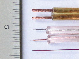
All Low Cost Wires Are Not the Same
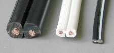 Here's some typical low cost wire that's available
today. The wire at the left with the heavy insulation is 12-gauge low voltage
cable that's used for garden lighting accessories. It's 1/2" wide and cost
28 cents/foot. The white lamp or extension cord is 16-gauge and is about
1/4" wide. It cost 25 cents/foot. The black wire at the right is
24-gauge" speaker wire" that came with a receiver. It's only 1/8"
wide. Although the 24-gauge wire is very small, it is only 8 feet long. That
works out to just 5% of the impedance for an 8-ohm speaker or 0.4 ohms.
Here's some typical low cost wire that's available
today. The wire at the left with the heavy insulation is 12-gauge low voltage
cable that's used for garden lighting accessories. It's 1/2" wide and cost
28 cents/foot. The white lamp or extension cord is 16-gauge and is about
1/4" wide. It cost 25 cents/foot. The black wire at the right is
24-gauge" speaker wire" that came with a receiver. It's only 1/8"
wide. Although the 24-gauge wire is very small, it is only 8 feet long. That
works out to just 5% of the impedance for an 8-ohm speaker or 0.4 ohms.
All of this wire is stranded and is easy to
work with. All the wires are coded so that you can maintain proper phasing of the
speakers. The smaller wire has a white stripe on the insulation of one of the
conductors. The 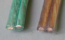 other two have ridges molded in the insulation
covering one of the conductors.
other two have ridges molded in the insulation
covering one of the conductors.
All inexpensive wires are not the same, However. This wire at the right was sold as speaker wire several years ago by such places as Home Depot and Lowes. It sold for 33 cents/foot. It had transparent insulation and was 12-gauge. It was much less expensive than the brand names. It did not have any coding to identify one of the wires for proper phasing. I had some of this wire for about 6 months and noticed it was turning color. Now it has turned a very pronounced green on the surface of the copper wire, indicating a chemical interaction with the insulation and the copper. A new piece of wire is at the right for comparison. Although the wire may not corrode any further, it doesn't inspire confidence, particularly if the insulation comes close to the connecting terminals.
Perhaps the transparent insulation was an attempt to mimic the more expensive speaker wires. Without researching the chemical properties of the insulation or the need to code one of the wires, it was not well thought out for use as speaker wire. I have heard complaints by others about the same problems. The normal lighting wires and wire supplied with the receiver shown above do not have these problems. I still have some of the #16 lamp cord that was used at the shows back in the 1970’s and it still shows no sign of oxidation, corrosion or patina.
![]()
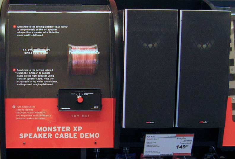
Thanks to Brian Goss, further information has been found about how a deceptive wire demonstration can inadvertently prove my point about how adequate wire size is the major factor in selecting a speaker wire. He found this demonstration at a Circuit City store in Houston. I found a similar demonstration in a local Circuit City store in Central Florida and took the above picture. Two speakers used for the demonstration are shown at the right side in the picture. The 50-foot reel of small wire is on the left and the 50-foot reel of large Monster wire is next to it. The idea it to connect 50 feet of each wire in series with each speaker and then switch from one to the other to hear differences.
Brian commented that “The speaker wire display has a switch to select between 'Monster' cable and 'Generic' cable. When you switch it to Monster cable it sounds about twice as loud. The sign reads, see how monster wire makes a difference, but they are not even comparing the same gauge of cable. I asked the salesperson about this and he claimed it wouldn’t matter.
When checking a roll of XP wire on the shelf, I found there was no indication of the wire size. Further checking on the Monster web site also showed no wire size or even resistance values. At another store that sold this wire, the sales person was more helpful. They also checked the roll of wire and the Monster web site to no avail. However, they called the sales representative, who said it was #16. Still unconvinced, the sales person compared the size of the copper in the XP and the copper size of a known wire. The Monster still looked larger until the ends of the wires were put right next to each other and then the copper size looked equal. It was an optical illusion. The insulation size was much bigger in the Monster, making the copper size look bigger as well.
The smaller reel of ordinary wire of in the demonstration appeared to be #24 but could have been even smaller. The resistance of 50 feet of 24 AWG wire calculates to be 1.28 ohms. The impedance of the speaker used in the demonstration is 8-ohms nominal impedance. The acceptable upper limit of wire resistance when used with an 8-ohm speaker is 5% or 0.4 ohms. Clearly, the #24 wire resistance is 3.2 times higher than it should be.
In comparison, 50 feet of the #16 wire is only 0.2 ohms and is better than the acceptable limit. The resistance of the smaller ordinary wire is 6.4 times the resistance of the Monster wire. The demonstration clearly proves that adequate wire size is essential to proper operation of a speaker. It does not in any way prove that the Monster brand is superior to ordinary copper wire of the same size. Even ordinary #16 zip cord will work just as well and is also 0.2 ohms for 50 feet.
A further problem with using too small a wire is not only that the speaker output decreases but also that the speaker response changes at various frequencies depending on how the speaker impedance varies with frequency. The response tends to follow the variations in the speaker impedance.
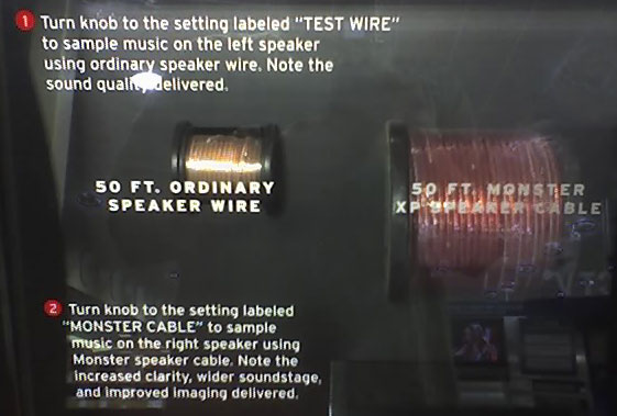
When making the listening test at my local store, I heard not only a lower level but also the change in response. To further confuse things, the monster wire could be heard only on the right speaker and the small wire only on the left speaker. The claims written on the display say “Turn knob to the setting labeled ‘Monster cable’ to sample music on the right speaker using Monster speaker cable. Note the increased clarity, wider soundstage, and improved imaging delivered.” I can’t say that I heard an increase in clarity and I definitely did not hear a wider soundstage and improved imaging. It may come as a surprise to the creators of the display but two speakers playing both stereo channels at the same time are needed to evaluate soundstage and imaging. Not only that, but even if both speakers were playing in stereo in this setup, having them right next to each other offers minimal stereo effect. Of course, we are told we will hear better clarity, etc. with Monster cable and, of course, believing is hearing. Thanks to Brian for the above picture from the Houston store.
Other sorts of trickery are used in the wire game. At the top in the above picture is ordinary #18 lamp cord with the normal amount of insulation. Below it is some speaker wire made in China by a place called Caries. The outside dimension of the insulation is much larger, yet the actual wire size is far smaller. First impression is that this is much heavier wire but after the insulation is removed, it is a different story. In fact, the wire diameter measures .014 inches, the same as the single piece of .#28 wire at the bottom of the picture.
![]()
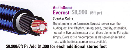
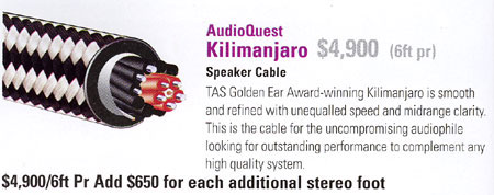
If you are looking for expensive speaker wire, this may be just what you are looking for. It was advertised in a 2005 catalog. I have not personally tested this wire and will leave it up to you to decide how much improvement it might make over ordinary wire in your system. For my 25 foot runs from the power amplifier to each speaker, I would need to spend $58,000 plus tax. After taking out a second mortgage on my house, you can bet I would want to hear an improvement, real or not.
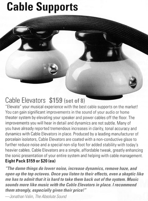
To supposedly enhance the sound of this wire, you can purchase these common power line insulators. The ad doesn’t say anything about the recommended spacing, but I gather that if the wire sags easily, many insulators would be needed. Being a collector of old glass and ceramic insulators that were used on telephone lines and power lines, I recognized these right away. The U-shaped top is referred to as a “cable” type. The small “foot” under the base is where the insulator screws on to a threaded wooden or metal peg on the power line cross-arm.
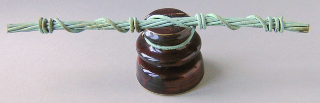
In the above picture, this old porcelain cable insulator is shown with the original copper wire used on a power line. The insulator is 3-1/4” in diameter and 3-1/4” high. The surface of the copper wire has turned green after many years of exposure to the elements. The U-shaped top was often used in windy areas and mountain terrain where a firm hold was needed. The U is where the cable is placed and a wire is wrapped around both insulator neck and cable to further hold it in place. The wide skirt is to allow water to drip off and reduce the conductive path to a power pole. This is important as the lines could be carrying 3,000 volts or more.
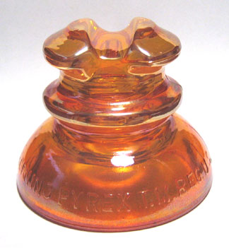
Many different companies such as Brookfield, Hemingray. Whitall Tatum and Corning made the cable type of insulators, along with many other shapes and sizes. They were made of glass in various colors, porcelain, plastic and even rubber. In this Corning Pyrex carnival glass version, you can see the threaded area inside. The insulator is 3-3/4” in diameter and 3” high. Pyrex and ceramic were needed for high voltages and could often be seen along railroads lines. When it rained or there was high humidity and leakage to the pole caused enough heat to be generated that could crack an ordinary glass insulator.
Perhaps you could find some authentic wooden cross-arms to mount the insulators on and then mount these assemblies along the walls—a real conversation piece.
Cable Trestle Suspension
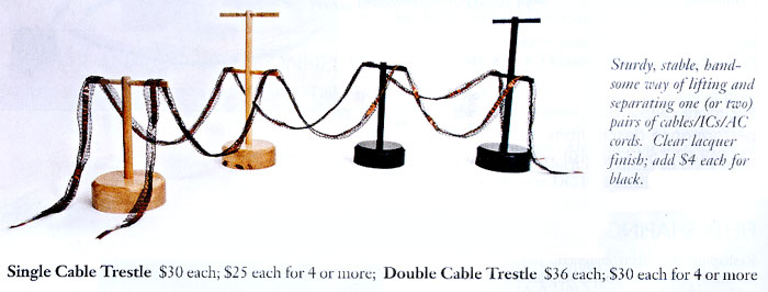
More nonsense! Alternately, you can now have a scientific display of power transmission lines in your own home. Some claim that you should not to run any wires near plastics or ungrounded metal surfaces such as artificial fiber rugs or curtains, tiles, linoleum, laminate wood floors, plastic moldings/wallpaper, urethane varnished floors, etc. If possible, keep wires at least 8” above rugs or 8” from plastic or ungrounded metal of any significant mass. These plastics are invariably terrible-sounding dielectrics.
I would think rather than having the cables resting directly on the trestles, the use of smaller glass insulators might be more appropriate. Another option might be to mount the trestles upside down on the ceiling and then hang the wires. This way, they cannot be missed by admirers. Wall trestles are also available but watch out for plastic moldings and that wallpaper!
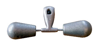
For those who want to go even further when suspending speaker wire above the floor, you might consider investing in a cable damper. Although originally conceived by the power industry to eliminate vibration caused by wind or high loads, a similar principle can be applied to vibration caused by lower frequency excitation of the wire in the listening room. The damper has two natural frequency modes commonly known as ‘flying’ and ‘wiggling’. It has a specially designed 19 strand messenger wire allowing the damper to dissipate vibration, or ‘wake up’, at lower energy inputs. The damper is normally placed near the end of each run from one insulator to the next. It can be attached to the cable at the top of the device. The damping portion hangs below the cable. The damper then becomes the equivalent of a mechanical anti-resonant tap to cancel out cable vibration.
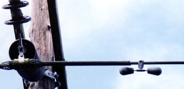
Although such a device is presently not known for home use, it would be no surprise it if a home style damper like this appears on the market sometime in the future. Although the damper is totally useless in the home, it could impress others as part of your system and your scientific expertise.
![]()

Wire advertising began many years ago. This ad appeared in the October 1953 issue of Audio Engineering magazine. In those days it meant that Belden made many different kinds of wires for different applications; some that were shielded, some for high voltage, some made into cables with multiple conductors insulated from each other, etc. There was no speaker wire back then.
![]()
Wire Conditioner
![]() Along with green magic markers on CDs and audio bricks
is another item called the wire conditioner. The claim is that unused wires do
not sound the same as wires that have been used for a period of time. The
device supposedly simulates what program material will do for the wire. This is
called a break-in period. The thinking is that, like a new pair of shoes that
are stiff when first put on, repeated use will make them more pliable and
therefore more comfortable.
Along with green magic markers on CDs and audio bricks
is another item called the wire conditioner. The claim is that unused wires do
not sound the same as wires that have been used for a period of time. The
device supposedly simulates what program material will do for the wire. This is
called a break-in period. The thinking is that, like a new pair of shoes that
are stiff when first put on, repeated use will make them more pliable and
therefore more comfortable.
It would therefore seem that used speaker wire and used audio and video interconnects would be worth more than the new wire and interconnects simply because they have been used already. There could be a big savings in time and expense by doing conditioning on your own or purchasing the device. Unfortunately, this is just another way of making money. It can be considered as another “quack” remedy machine.
Of course, after spending this much money on the device, believing-is-hearing may be the prime factor. So what is needed is another controlled, instant-comparison listening test where one wire is conditioned and another wire from the same roll of wire is not conditioned.
This contrived need for conditioning would seem to offer a new sales feature for wire by selling pre-conditioned wire that has already been accomplished by the factory. However, this could be countered by another statement saying that the wire must be conditioned or “tuned” using your own unique system and that conditioning with other systems or devices will not produce satisfactory results.
My favorite question still is—how short can the conditioned wire be before any difference is no longer heard?
![]()
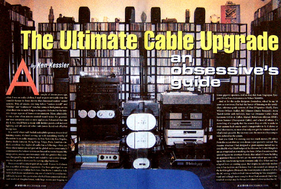
To add to the questionable claims about speaker wire, even the AC wiring in your house has been accused of influencing the sound we hear. Ken Kessler has written an article titled "The Ultimate Cable Upgrade" published in Audio, December 1999. He claims that differences in sound can be heard with different kinds of house wiring. He also claims house wiring requires a "burning-in" period.
To quote from page 34:
"In thirteen out of fourteen sessions, the standard house wiring was judged to be the least satisfactory: less detailed, less open, less dynamic. So convincing are these results that I have no qualms about recommending top grade AC wiring in place of the standard stuff, provided that the wiring is professionally installed."
Three "audiophile" cables and one conventional AC cable were installed in his house by an electrician.
He goes on to say:
"What also emerged, though, was that there was no clear winner among the audiophile cables. Rather, I learned that one worked better with solid state equipment, another with tubes. One was outstanding with digital sources but not with turntables."
The author has made the faulty assumption that all wire can have an influence on the sound, no matter where it is used in the system and including the house wiring. It is difficult to understand why the relatively short lengths of internal house wiring can make a difference, when wire in the power lines, right through the distribution transformer in the back yard and stretching for miles and miles to the generating station, does not influence the sound. Even more surprising is that high power lines are not even made of copper. They are made of aluminum reinforced with steel! Perhaps the power line insulators should be considered as well. This reminds me of the comparison with speaker wire where the voice coil wire is ordinary copper wire that is far longer than the wires from the amplifier to the speakers.
The author has cleverly used words such as "detailed", "open" and "dynamic" to describe the sound. These are not measurable quantities. However, dynamic could be interpreted as a higher peak power. But in the article, all the components remained on the same line except the CD player. This eliminates the possibility of any listening differences for the power amplifier and other components in the system.
A favorite question of mine for those who claim they can hear differences is "how short does the wire have to be made before differences can no longer be heard?"
In any A-B comparison test, instant comparison is of paramount importance. The delay in switching the CD player from one power outlet to the other was said to be 30 seconds. This is more than sufficient time for the subjects in any listening test to have forgotten what they had heard, particularly if the differences are very small or non-existent.
Of course, claims for the listening differences are in the same category as the claims for exotic speaker wire. It is money oriented and in this case it is to sell magazines.
Perhaps, someday, Ken Kessler and several other audio perverts will condescend to take a controlled listening test. Several offers have been made for anyone who can correctly identify a particular kind of wire under controlled conditions. Challenges offering $15,000 or more have not even been tried by these “experts,” Ken could be a rich man if he could consistently identify differences in house wiring with controlled tests. I would encourage him to prove his abilities for the readers of Audio magazine who deserve the truth! (Webster’s defines perversion as: “to cause to turn aside or away from what is good or true or morally right: CORRUPT)
Don’t forget all the wires used inside your preamplifier, power amplifier, etc and even inside your speaker system. Are they audible as well?
![]()
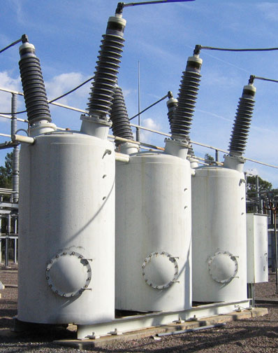
Of course, Ken did not mention what audible difference power distribution systems could make. No speaker wire is used here. Of course, if his power were taken from a 3-phase line, there could be all kinds of phase problems in the audio. Further, this in turn could be audible even if only one or two phases were used, depending on which ones. We know that solar storms can influence power lines and cause overloads. Therefore solar activity can influence sound in house wiring and possibly even speaker wires---and if you believe all of this, then pigs can fly!

Courtesy of Pink Floyd’s ANIMALS
![]()
There is big money to be made in wire, not only speaker wire but all kinds of exotic wire—hookup wire, audio cables, power cables and a wide variety of speaker wire including the new term of “speaker cables.” The term cable implies more robust and heavy duty qualities than wire.
I have learned from one wire company that much of this exotic wire is not manufactured in the USA at all. It comes from places like Taiwan and China. It can be bought in industrial quantities at surprisingly little cost and sold for tremendous profits. Custom runs in large quantities, can be purchased having any number of different features and are not a problem for versatile wire manufacturers. It can even be made with various terminals already installed.
The strategy in selling these products is, in part, to appeal to those who are looking to impress others with something unique and expensive. There is also pride of ownership and the belief that if it costs that much it must be good. It reminds me of the Percy Bysshe Shelley poem Ozymandias but for speaker wire it translates to “Look upon my expensive wires ye mighty and despair.” It will always sell to those who want the latest thing and would spend as much for a Rolex watch as they would for wire. Of course, there are ordinary watches that will tell time accurately they but don’t have that name or that price.
Another part of the strategy is to capitalize on the lack of truth in advertising, particularly the whole truth. Perhaps the two words “truth” and “advertising” are on opposite extremes but half of the truth can be worse than a lie. I don’t think the average consumer is any match to cope with the persuasive sales “hype” of professional salesmen praising a questionable wire science and doubtful benefits.
When confronted with the truth, believers do not want to hear about it. They want to remain in the magical world of fantasy where they think they can hear improvements in their wire, often arrived at by making listening tests without adequate controls or understanding of the problems involved including speaker impedance and amplifier stability. One of the prime tools in creating such a faith for the average consumer is by capitalizing on fear and ignorance as in many other things that aren’t readily apparent. There is fear that the wire currently in use is not good enough. There is ignorance because most people do not have scientific knowledge in this area and lack adequate measuring equipment to prove otherwise.
![]()
Logical Conclusions?
We have been told by advertising that the exotic speaker wires offer fabulous advantages over ordinary lamp cord. It would seem reasonable that using this same wire for lamps would also enhance their performance. In the same vein as wire literature, you can have your lamp reproduce light with the full spectrum color fidelity of natural daylight, finally allowing you see light the way it should be seen and bring out the natural performance of your lamp. It could offer greater warmth, detail, brilliance, definition and speed by providing wider bandwidth and reduced skin effect. It can provide a distortion free illumination that reduces eye strain, resulting in clearer vision and optimal color perception. It can allow you to work for longer periods of time with less visual distraction or fatigue. Just imagine what it might do for your electric razor or microwave, etc.!
Alternate Source of Speaker Wire?
Excerpts from this humorous article are from Collier’s magazine March 3, 1951.
|
|
|
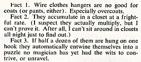
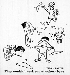
Here is a solution for what to do with those old wire clothes hangers. Use them for speaker wire. This has already been done and proved successful. By cutting off the hook and curled portion, the remaining wire can be easily straightened out. Then by cleaning the ends and wrapping one end of the hanger to another one, the connection can be soldered. The length can be made to suit. Be sure each hanger wire to the speaker does not touch the other one.
Listeners agreed the hanger wire sounded
excellent. In several A-B a listening tests using music, a comparison to
Monster cable showed that it was not possible to determine which was connected
and which sounded best. Several links can be found on google concerning this
test.
Bear in mind that power transmission lines
and telephone lines are reinforced with steel strands.
To test out this claim, the clothes hangers that I used are made of 12 to 14 gauge steel wire. There doesn’t seem to be a wire table for the resistance of steel coat hangers and there are all kinds of steel wire. However, using a reliable ohmmeter, one stretched-out hanger of 41 inches measures 0.05 ohms. This comes out to 0.0146 ohms per foot and 10 feet is then 0.146 ohms. That in turn says that 17 feet of two conductor hanger wire presents 0.5 ohms of resistance and could be an acceptable value for connection to an 8-ohm speaker. How does it sound? Try it!
![]()
![]()
Copper Theft
With the increase in the price of copper and the increase in copper theft, there might be some concern for those who own expensive speaker wire. Thieves are even looting outside air conditioners and plumbing pipes in homes just for the copper tubing. That expensive speaker wire can be the next target for robberies and it is even easier to disconnect. You can get extra insurance for jewelry and other special items, why not $15,000 speaker wire? Of course, those of us, who use ordinary wire, would not suffer any great financial loss and would not be burdened with the extra cost of insurance.
|
http://www.engadget.com/2008/03/03/audiophiles-cant-tell-the-difference-between-monster-cable-and/ http://rationalwiki.org/wiki/Audio_woo#Magical_cables https://www.youtube.com/watch?v=3UQDTZcpsDE
|
|
More text and pictures about McIntosh will be added as my research continues. Any comments, corrections, or additions are welcome. |
|
|
Created
by Roger Russell |