Welcome to Roger Russell's
McIntosh Equalizer History Part 4
The MQ107, MQ108, MQ109 and the
XRT26 Speaker system
Copyright
1996-2003 by Roger Russell
All rights reserved
No portion of this site may be reproduced in whole or in part
without written permission of the author.
![]()
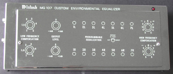
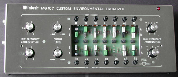
MQ107 Environmental equalizer
|
From experience with the MQ104 equalizer, we find that more adjustments
are needed to correct for some very bad room environments. Some dealers begin
to use two MQ104’s in series to solve some problem situations. |
|
|
|
The finish is shiny chrome with white lettering. Two screws hold the top cover in place. When this is removed, the controls and capacitor sockets are accessible. A red led indicator shows when the power is on. The unit can be turned on and off by the switched outlet in a preamplifier. |
|
|
|
|
Specifications
Frequency Response: 20Hz to 20,000Hz +/-
0.5dB
Hum and Noise: 90dB (79uV) below 2.5V
flat response. 85dB (140uV) below 2.5V worst case.
Harmonic and Intermodulation Distortion:
less than 0.02% at 2.5V output 20Hz to 20,000Hz
Low frequency Compensation: Variable from
0 to +17dB at 20Hz
Input Sensitivity: 2.5V into 27k ohms for
rated output with controls set for flat response
High Frequency Compensation: Variable
+/-10dB at 20,000Hz
Output Level and Impedance: 2.5V into 10k
ohms or more with the output level at zero and all other controls set for flat
response.
Programmable Filters: 14 sections (7 per
channel) each of which can be programmed for standard 1/3 octave center
frequencies from 20Hz to 1000Hz. Filter bandwidth is programmable for narrow
(approx. 1/3 octave) or wide (approx. 1 octave). Amplitude is continuously
adjustable +/- 12dB for narrow and +/-15 dB for wide. A detented control is
used to position for flat response. Programming is achieved by means of plug-in
capacitors provided with the MQ107.
Size: 3-1/2” high, 5-3/4” wide and 14”
long
Finish: Chrome and black
Weight 7 lbs. 9 oz.
![]()
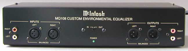
MQ108 Custom Environmental Equalizer
|
|
|
|
|
|
|
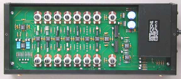
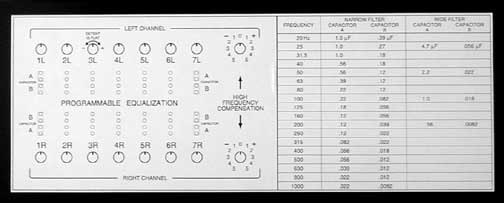
As in the MQ104 and MQ107, The frequency for each filter can be
adjusted using capacitors supplied in a kit. Capacitors are selected for each
frequency using the Frequency Programming Table. A diagram and frequency
-programming table are located on the underside of the top cover as well as
in the manual. The diagram shows the location of the holes for the capacitors
and function of the controls. See my page about equalizers
Part 2 for more details about the programming table and the capacitor
kit. |
|
|
Specifications
All specifications are valid with the MQ108 set for flat response
Frequency Response: 20Hz to 20,000Hz +0,
/- 0.5dB
Rated Output: 2.5V at main and balanced
outputs
Output Impedance: Main 250 ohms, balanced
100 ohms
Total harmonic Distortion: 0.002% maximum
from 20Hz to 20,000Hz at rated output
Power requirements: 120 volts 50/60Hz, 5
watts
Sensitivity: 2.5V for 2.5V rated output
Signal to noise ratio, A Weighted: 105dB
below rated output (95dB IHF)
Maximum Input Signal: High Level: 8 volts
Input Impedance: 22,000 ohms
High Frequency Compensation: +/- 10dB at
20,000Hz
Programmable Filters: 14 sections (7 per
channel) each of which can be programmed for standard 1/3 octave center
frequencies from 20Hz to 1000Hz. Filter bandwidth is programmable for narrow
(approx. 1/3 octave) or wide (approx. 1 octave). Amplitude is continuously
adjustable +/- 12dB for narrow and +/-15 dB for wide. A detented control is
used to position for flat response. Programming is achieved by means of plug-in
capacitors provided with the MQ107.
Size: 2.875” high, 5.65” wide and 13.6”
long
Finish: black
Weight 5-1/2 lbs. (2.5 kg) net, 6-1/2
lbs. (3.0 kg) in shipping carton.
![]()
MQ 109 and MQ109B Environmental Equalizer
This is the last equalizer to be made for McIntosh loudspeaker systems. The XRT26 was designed and produced without any requirements for an equalizer. However, because of customer complaints about the sound, particularly in Japan, the only way the system would be accepted was if an equalizer was included. The MQ109 was designed to correct, in part, the response of this system. However, instead of making the equalizer for use ONLY for the XRT26 and having no adjustments, it was decided to make it a more universal device that would roughly compensate for some room acoustics. The frequencies are based on an earlier equalizer that I specified in the 1970's but it never went into production.
The MQ109 center frequencies are selected to compensate for objectionable areas where the XRT26 has too much or too little output. These center frequencies are not adjustable. However, the amplitude and width of the frequency bands are adjustable and can boost or cut.
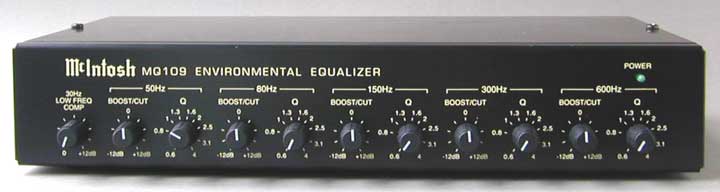
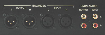
The MQ109 has the basic low frequency compensation that was used in the original MQ101 design for the qverdamped woofer. In addition, there are five equalizer bands centered at 50Hz, 80Hz, 150Hz, 300Hz and 600Hz. The variable “Q” control for each frequency can be varied from narrow (Q = 4) to wide Q = 0.6). Both balanced and unbalanced input and output connectors are provided. The equalizer must be connected between the preamplifier and power amplifier. The power switch and power receptacle are located on the right side.
Specifications
Frequency Response: 20Hz to 20,000Hz +/- 0.5dB with controls set to flat
Total Harmonic Distortion: 0.004% from 20Hz to 20,000Hz at rated output
Signal to Noise Ratio A weighted: 100dB below 2.5V flat and 98dB below 2.5V
worst case settings
Maximum Voltage Output: 6.5V from 20Hz to 20,000Hz
Output Impedance: 600 ohms balanced and unbalanced
Sensitivity: 2.5V with controls at flat position
Input Impedance: 47k ohms
Maximum Input Signal 2.5V
Low Frequency Compensation: =12dBaximum at 30Hz
Equalizer Center Frequencies: 50Hz, 80Hz, 150Hz, 300Hz and 600Hz (+/- 5%)
Boost/Cut Range +/- 12dB at center frequency (+/- 5%)
Q Control Range: 0.6 to 4 (+/- 5%)
Power Requirements: 120V 50/60Hz at 7 watts
Dimensions 12.4” wide, 7.3” deep and 2.3” deep
Weight 6 lbs net
Why was the MQ109 needed for the XRT26 and not the XRT20 or XRT22?
|
These comments are my opinions based on engineering facts and do not include the reasoning for any marketing strategy that may have been involved at that time. |
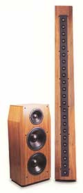
 My design
for the XRT20 and XRT22 bass cabinets is a wide credenza shape that is
relatively thin with angled sides. The XRT22 is shown at the left. This
interfaces very well with the room walls. However, the XRT26 bass cabinet,
shown at the right, is deeper by 3 inches and narrower by 5-1/2”. It has
straight sides. The result is response irregularities in both bass and
mid-range. These changes were made after I left McIntosh. See my section about column research.
My design
for the XRT20 and XRT22 bass cabinets is a wide credenza shape that is
relatively thin with angled sides. The XRT22 is shown at the left. This
interfaces very well with the room walls. However, the XRT26 bass cabinet,
shown at the right, is deeper by 3 inches and narrower by 5-1/2”. It has
straight sides. The result is response irregularities in both bass and
mid-range. These changes were made after I left McIntosh. See my section about column research.
 Later,
management decided to try and correct the problems with an equalizer. It should
be noted that although equalization can compensate for a deficiency in speaker
response at a particular location in front, it cannot compensate for all points
around a speaker if the speaker has directional problems. For example: if the
response at one position needs a boost in the area of 300 Hz to make it the
same amplitude as adjacent frequencies, this adjustment can affect other
positions around the speaker adversely and produce a peak in response at 300
Hz.
Later,
management decided to try and correct the problems with an equalizer. It should
be noted that although equalization can compensate for a deficiency in speaker
response at a particular location in front, it cannot compensate for all points
around a speaker if the speaker has directional problems. For example: if the
response at one position needs a boost in the area of 300 Hz to make it the
same amplitude as adjacent frequencies, this adjustment can affect other
positions around the speaker adversely and produce a peak in response at 300
Hz.
Other factors that may have influenced customer dissatisfaction.
The tweeter column is designed for use against a wall away from reflecting surfaces. Response will be altered if the bass cabinet is placed too close to it. Yet, in order to maintain a coherent image, the center of the bass cabinet and the center of the tweeter column must be less than 36” apart. To minimize reflections from the sides of the bass cabinet, the XRT20 and XRT22 sides are angled. There is only a minimal 5” of cabinet side to reflect.
The XRT26 sides are not angled and have 15-1/2” to reflect. The reflections result in uneven high frequency response and poor high frequency imaging, particularly for the listener in a sitting position. Wall mounting for this system is unsatisfactory
An alternate solution for homes, where wall mounting is not possible, is to mount the columns on stands. This means the column will be spaced away from the wall due to baseboard thickness or maybe baseboard heating. As the columns are moved forward away from the wall, unwanted reflections from the XRT26 cabinet decrease. However, as the column is moved even a few inches away from the wall, the response changes due to diffraction of the lower tweeter frequencies around the edges of the column. Sound strikes the wall behind it and is reflected back out of phase with the direct sound. This disturbance gradually decreases as the column is moved further away from the wall. By the time the distance from the wall reaches one foot or more, the effects are minimal. Reflections from the XRT26 cabinet are then also reduced.
A two-position crossover adjustment switch at the rear of the XRT26 bass cabinet is used in an attempt to correct for bass cabinet reflections when the column is on the wall. However, reflections from the XRT26 cabinet are directional. Crossover changes introduced by the switch cannot correct this directional response effectively. The other position is for when the column is a foot or more away from the wall.
The column width also affects the lower portion of the tweeter response whether it is against the wall or not. The XRT20 and XRT22 columns have the same width from top to bottom. The response is adjusted using the crossover network to be compatible with this column width. The response is uniform from top to bottom. The XRT26 has a tapered width tweeter column. It is narrow at the top and wide at the bottom. The response changes with listening height. This is totally unacceptable and can be clearly heard and measured. The crossover cannot compensate for the changing width except at only one listening height.
The XRT26 tweeter column incorporates 1” aluminum dome tweeters. Aluminum typically has a characteristic sound. See my Drivers page about Aluminum Domes VS Soft Fabric Domes.
![]()
|
The Equalizer History is divided into four parts |
|
|
The ML-1C Speaker, MQ101 and MQ102 Equalizes |
|
![]()
|
About This Site |
||
|
|
More text and pictures about McIntosh will be added as my research continues. Any comments, corrections, or additions are welcome. |
|
|
|
|
Created by Roger Russell |