McIntosh Equalizer History Part 1
by Roger Russell
The ML-1C Speaker plus the MQ101 and MQ102 Equalizers
No portion of this site may be reproduced
in whole or in part
without written permission of the author.
![]()
What's On This Page?
![]()
What's the McIntosh Equalizer All About?
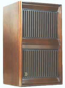
The McIntosh Environmental Equalizers all began with my first patent number 3,715,501 "Loudspeaker System". The McIntosh ML-1C loudspeaker system consists of the ML-1C speaker (above) and the MQ101 equalizer (below). Together they form a complete system that can maintain flat response down to 20Hz within 1dB. No subwoofer is or was needed! The system works just as well today as it did in 1970.
There are equalizers and equalizers. They aren't all the same. There are speaker equalizers that work with a speaker system to achieve a specific acoustic output. There are equalizers that compensate for different speaker locations in a room. There are equalizers that compensate for response peaks and dips due to room resonances. There are also program equalizers (tone controls) that adjust the frequency balance of program material. Each kind of equalizer is tailored to accomplish a specific task. Each covers a specific frequency range with a certain shape and amplitude. A bass control, for example, does not make a good speaker equalizer. It’s too broad and while it may correct one frequency range, it can also exaggerate another, resulting in different bass that still doesn't sound good.
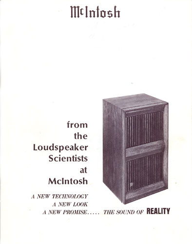
There were no owner manuals for the ML systems.
However, Gordon Gow wrote this 20-page brochure
to introduce the ML loudspeakers, room acoustics and the equalizer.
McIntosh P349 Loudspeaker Switching Console
Although the ML-1C is more efficient over most of the frequency range, it has less relative output in the deep bass range compared to other systems. The equalizer provides the other half of the design to achieve an outstanding bass response to 20Hz that no other system that size can reproduce by itself. A required equalizer could have been a problem to demonstrate the ML-1C in stores. A solution for McIntosh dealers was the P349 Loudspeaker Switching Console.
 The P349 is a
switching device that allows the user to select any pair of loudspeakers from a
total of 8 pairs. All pairs are driven from a single program source consisting
of a preamplifier and power amplifier. The McIntosh MQ101 and MQ102 or
equalizers of other manufacturers can be connected between the preamplifier and
power amplifier on any of the 8 speaker switch positions. Slide switches on the
rear of the chassis can be set to by-pass the signal for speakers that are not
designed to operate with an equalizer. Individual
level controls are provided for the left and right channels for each speaker
selector so they can be adjusted for equal acoustic output from each speaker.
The P349 is a
switching device that allows the user to select any pair of loudspeakers from a
total of 8 pairs. All pairs are driven from a single program source consisting
of a preamplifier and power amplifier. The McIntosh MQ101 and MQ102 or
equalizers of other manufacturers can be connected between the preamplifier and
power amplifier on any of the 8 speaker switch positions. Slide switches on the
rear of the chassis can be set to by-pass the signal for speakers that are not
designed to operate with an equalizer. Individual
level controls are provided for the left and right channels for each speaker
selector so they can be adjusted for equal acoustic output from each speaker.
Speaker switch contacts have heavy-duty solid silver contacts rated at 6 amps, which can handle large amounts of audio power. The switch positions are inter-locked so that only one pair of speakers can be played at a time. The speaker grounds for the left and right channels are isolated from each other. An additional P349 console can be connected to the first console to expand the switching system to 16 pairs of speakers. An 11-pin socket at the rear panel provides 6.3 volts for lighting lamps that can be located on the speakers to indicate which speakers are playing. Pin #1 is for position #1, pin #2 is for position #2, etc. Pin 10 is a common ground.
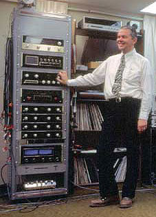
Here I am demonstrating the ML-1C in our listening room at plant 5. Four MQ101 equalizers are mounted under the console to be used with McIntosh speakers. When recordings containing deep bass are played, the benefits of the ML-1C system can clearly be heard.
To further complicate matters, the equalizers were sold separately from the speakers instead of being included in the price of the system. This was a fatal mistake to preserve the integrity of my design. The equalizer was treated as an optional enhancement instead of an essential part. Granted, the MQ101 selling price of $250 would add more to the cost of $624 for a pair of ML-1C systems.
The alternate is the MQ102 equalizer that provides the same required low frequency equalization but without a high cost. It had a price tag of only $74.50. The McIntosh MQ101 and MQ102 equalizer advantages were apparently never completely understood by some sales people or the customers. At that time, manuals for all electronics equipment were written at Plant 3. The equalizer manuals explain how they are to be connected and how the different knob positions adjusted the equalizer response. There is no further explanation of the benefits of the equalizer that was part of the ML-1C system.
Over the years, only one person in three bought an equalizer and those without it never had the full benefit of the design that consequently lacked bass response compared with other systems on the market. Purchasing the equalizer for use with other brands of speakers was not recommended. The increase in deep bass power could damage a system that would not handle the increased power demands and it would also produce the wrong bass response. There may have also been reluctance by the customer to insert any devices in series with the power amplifier input for fear of generating distortion or some other imagined problem. However, equalizers are used in many different parts of the audio chain but it may be that they are part of an integral unit like the RIAA phono section in a preamp and not as an external attachment. A more detailed explanation of the benefits of the equalizer for the customer may have helped to sell more of them but the equalizers were still not included with the system price.
I decided to write individual manuals for the new series of XR systems and with the help of my boss, Sidney, arranged for them to be processed at plant 3. That included the XR3, XR5, XR6, XR7 and XR14. They contained more pictures and text that emphasized how the speaker and equalizer work together for acoustic response and speaker location in the room.
![]()
Magnetic Field Strength and Woofers
To help understand why the ML-1C woofer is different, here is a little background information about loudspeakers. In 1978, when I was running some response tests on a sample woofer, I had accidentally touched the input lead to the MC75 (75 watt) amplifier that was connected to it. Of course, there was the familiar but unexpected loud 60Hz buzz that comes when making a mistake like this. There was also concern that the woofer might have suffered burnout or some such thing. However, it continued to respond with a low power sine wave sweep test but I noticed that something had changed. The response was not the same anymore and the output was lower. I checked the driving voltage and that was the same so it had to be the woofer.
It turns out that the high 60Hz buzz power was sufficient to partially demagnetize the woofer magnet. This particular magnet was alnico and also served as the pole piece inside of the voice coil. Although demagnetization is known to occur with alnico magnets, I had never experienced this actually happening. In comparison, barium ferrite (ceramic) magnets that we used in all of the production systems had a hysteresis loop that was much too high and linear to be affected.
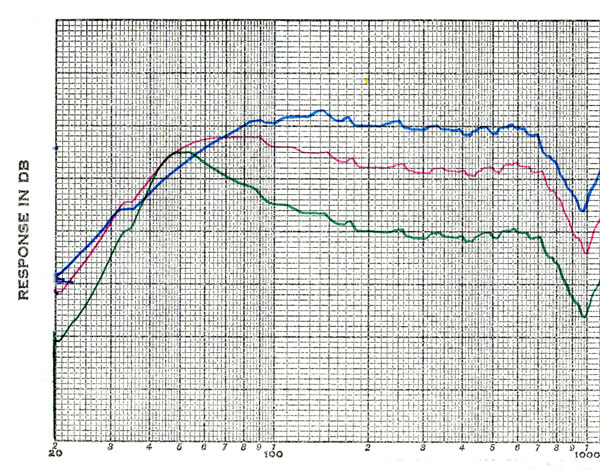
The blue curve was the original response of the woofer with normal magnetization. This is often the response curve used in some sealed system designs because the woofer has higher output in the upper bass and can cross over to a mid and tweeter that also have higher output. The resulting system has a higher efficiency and will play louder. This can be significant as a selling feature compared to other systems. However, the relative deep bass response is deficient. The blue curve is closer to the response of the ML-1C overdamped woofer that actually begins to roll off starting at 150 Hz.
The red curve is after the first 60Hz burst. The resulting response increases slightly from 30 Hz to70 Hz but decreases about 4 dB over the rest of the woofer range. An advantage for a system like this is for greater lower bass output but requires crossing over to a mid and tweeter having lower output. The result is a lower efficiency system but with exaggerated lower bass that can be preferred by some users. The 4dB loss means that more than twice the power is needed for the same listening level, except for the lower bass.
Then I deliberately touched the input lead again and brought the response way down shown by the green curve. An underdamped system like this would be completely useless with a response peak of about 8 dB at 50Hz and 10 dB lower output through the rest of the frequency range .
Meanwhile, for all three examples, the resonant frequency of the woofer in the box remains the same at 50 Hz. So this means that the system resonant frequency of a sealed system does not always indicate what the low frequency response will be. The BL product is used for T-S parameters. The L, or length of voice coil wire in the magnetic gap, remains the same but the B flux density in the magnetic gap is the variable. I was able to restore the woofer to normal performance by recharging it in the lab magnetizer.
In 1982, we had an opportunity to make another interesting experiment. One of the fellows working for me came across an old speaker with a field coil that provided magnetization instead of a permanent magnet. This was typical for older radios. I thought it would be interesting to restore the old speaker so he took out the old cone assembly and put in a new cone assembly including a foam surround. We had an adjustable DC power supply in the lab to power the field coil. Then he ran response curves with various amounts of current in the field coil to give various flux densities in the magnetic gap. We used a Bell flux meter probe and inserted it in the voice coil gap to gain additional data.
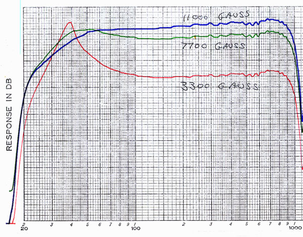
Again, this gives a nice indication of what happens with varying magnetic flux in the voice coil gap. The blue curve is the response of the rebuilt woofer and the voice coil gap has a flux density of 11,000 gauss (1.1 Tesla). The green curve is after decreasing the field coil current. This in turn reduces the gap flux density to 7700 gauss (0.77 Tesla). The resulting response increases below 60 Hz but decreases about 2 dB over the rest of the woofer range. A further reduction in field coil current brings the response way down as shown by the red curve. This reduces the flux density to 3300 gauss (0.33 Tesla). Meanwhile, for all three examples, the resonant frequency of the woofer in the box remains the same at 39 Hz.
As an interesting note, varying the moving mass of the woofer instead of the magnetic flux will give a similar set of response curves with reduced output but with an important difference. The resonant frequency will shift lower and lower as the mass is increased.
Going Outside of the System
 In the design of normal
speaker systems there is a tradeoff between efficiency, box size and low frequency
cutoff. This is all in accordance with the Thiele-Small parameters and
Hoffman's Iron Law (See Note 1). Low frequency response is normally desired to
be as flat and extended as possible. This can be done with either a very large
box or a very inefficient speaker. A large box is expensive and usually not
compatible with room decor. An inefficient speaker requires a large power
amplifier, which is expensive and places excessive demands on the speaker power
handling ability. Therefore, design of a speaker with flat response to 20Hz
would seem to be impractical. The final choice is invariably a compromise.
Typically, a sealed system is designed to extend response down to system
resonance, which is often around 50Hz. It is typically an underdamped system
having a Qts ranging from 0.7 (green
curve below) to 1.0 (blue curve below).
In the design of normal
speaker systems there is a tradeoff between efficiency, box size and low frequency
cutoff. This is all in accordance with the Thiele-Small parameters and
Hoffman's Iron Law (See Note 1). Low frequency response is normally desired to
be as flat and extended as possible. This can be done with either a very large
box or a very inefficient speaker. A large box is expensive and usually not
compatible with room decor. An inefficient speaker requires a large power
amplifier, which is expensive and places excessive demands on the speaker power
handling ability. Therefore, design of a speaker with flat response to 20Hz
would seem to be impractical. The final choice is invariably a compromise.
Typically, a sealed system is designed to extend response down to system
resonance, which is often around 50Hz. It is typically an underdamped system
having a Qts ranging from 0.7 (green
curve below) to 1.0 (blue curve below).
If we accept these rules as a limit, then it's as far as we can ever go with speaker systems, and golden opportunities are being missed. What if we go outside the system and cheat? Like in the movie Star Trek "The Wrath of Kahn" (1982) we learn that early in the film Captain Kirk is able to change the scenario by going outside the accepted limits and changing the conditions from what was otherwise a no win situation.
In the ML system design, that's what I did. I designed an overdamped woofer that has a very high BL product and used it in a small sealed enclosure. This is where the equalizer came into being. I created an electrical equalization circuit that is just the opposite of the speaker rolloff. Wherever the response is down, the equalizer is up by an equal amount, effectively maintaining a flat response for the speaker and equalizer combination. What is nice about this concept is that the equalization continues to correct for response right through the system resonance and right on down to 20Hz and below. Electronic equalization is made prior to the power amplifier so there are no losses or load impedance problems introduced between the power amplifier and the speaker. That is what my patent is all about. The amount of acoustic material in the enclosure is chosen to provide a smooth continuous response through the system resonance, which is about 50Hz. The Qts is about 0.4 (red curve) in the above graph. Efficiency is much higher in the upper bass, but response begins to roll off as high as 200Hz.
The ultimate slope of the low frequency rolloff for all sealed systems is 12dB/octave. As a system becomes more underdamped, there is a greater tendency for it to ring. It means the cone motion does not stop when the signal stops. It keeps on moving and gradually decays. Critical or overdamped systems have no tendency to ring. The overdamped approach is not normally a good design because it has relatively few low frequencies compared to the upper bass.
I chose 20Hz as the limit and it begins to roll off frequencies below there. There are several reasons for this. At the time there was turntable rumble, record rumble and tonearm resonance. There was also the cone excursion limit to be considered. Each octave lower means four times the cone excursion. Even though the equalizer is rolled off below 20Hz, it does not just suddenly die. There is still some response even at 10Hz. The system is just not flat any more. Today, where CD's and other means of recording are no longer plagued by rumble, arm resonances etc., flat response can be extended down even further. Of course, the woofer must still not be overdriven.
![]()
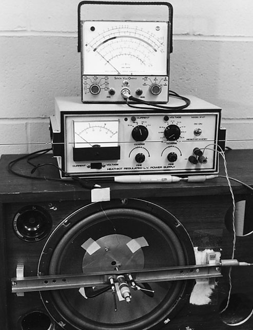
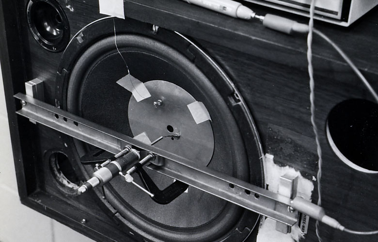
I devised an interesting test for linearity. I set up a micrometer supported by a metal U-shaped strip that is centered on the woofer. A metal plate is attached to the woofer cone with masking tape. A rigid metal piece that is pointed projects from the center. A thin flexible wire runs from the plate to an ohm meter. To complete the circuit, the other lead from the ohm meter is clipped to the U-shaped strip and the metal micrometer. When the micrometer probe touches the small metal piece on the plate, the circuit is complete and a low resistance is indicated on the ohm-meter instead of an open circuit.
Starting at rest position for the woofer cone, small increments of current are fed to the voice coil from a DC current supply. When the cone moves in, the micrometer can be advanced until contact is made again and the distance measured. When the current polarity is reversed, the micrometer is retracted ahead of time and then advanced to make contact again.
The final step is in plotting the graph of current versus displacement. Some woofers form a beautifully shaped “S” curve in the rage of current used for the test. Others were more linear in the same current range.
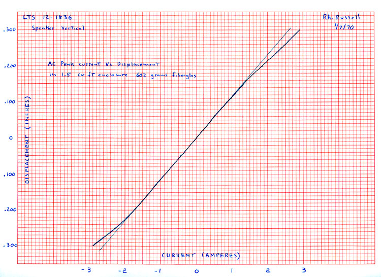
Then, I also made a dynamic linearity test using a power amplifier and 20Hz test signal. By using a pointed metal piece in a hook-shape and attaching a metal disc to the micrometer, I could measure the backward motion as well as the forward motion. When the pointed piece just touched, a displacement reading could be taken. Here is the curve I made back in 1970 for the custom CTS sample 12” overdamped woofer. The linear portion of the curve can be clearly seen. The curve increasingly departs from linear as the voice coil moves further out of the magnetic gap. In addition, this test also took into account the linearity of the cone suspension including the spider and surround.
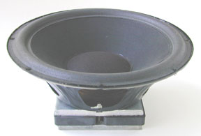 In my final 12"
woofer design I use a 2" high temperature four-layer voice coil wound on a
black anodized aluminum voice coil form that helps to dissipate heat. The
magnet structure has two 6" X 6" X 1/2" steel plates and a 54 oz
barium ferrite magnet. The woofer can make half an inch peak-to-peak excursion
completely linear. To prevent the voice coil from bottoming, the back plate is
machined out 1/4" deep in a circle where the voice coil could hit. With
the revised back plate, it can then easily make a 3/4" peak-to-peak
excursion without hitting but it is not quite as linear.
In my final 12"
woofer design I use a 2" high temperature four-layer voice coil wound on a
black anodized aluminum voice coil form that helps to dissipate heat. The
magnet structure has two 6" X 6" X 1/2" steel plates and a 54 oz
barium ferrite magnet. The woofer can make half an inch peak-to-peak excursion
completely linear. To prevent the voice coil from bottoming, the back plate is
machined out 1/4" deep in a circle where the voice coil could hit. With
the revised back plate, it can then easily make a 3/4" peak-to-peak
excursion without hitting but it is not quite as linear.
The tinsel leads that connect to the voice coil are brought out on opposite sides of the basket for good dynamic balance and are a unique feature of the McIntosh woofers. Another reason for doing this is that I found if both tinsel leads are brought out on the same side to a commonly available dual terminal strip, the leads can touch at high power and burn out.
I use a urethane surround. I found that rubber surrounds were unsatisfactory for several reasons. The added mass to the moving parts lowers the output by several dB. The rubber surround is only available with a small roll. This limits the excursion that I need. The heavy rubber roll introduces resonances of its own. I also tried a cloth roll surround. This collapses and goes inward at long outward cone excursions and makes a cracking noise like a whip. I thought it was the voice coil bottoming until I saw it with a strobe light. See my McIntosh Drivers History page for more information about this woofer and other McIntosh drivers.
When the system is combined with a crossover coil, Hookup wire and amplifier, the combined resistance in the circuit brings the system Q to about 0.5, or critical damping. Another distinct advantage with a more efficient woofer is that a more efficient mid-range and tweeter can be matched with the upper bass output of the woofer.
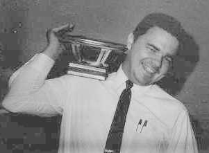
Here I am happily involved with the first prototype design of the 12" ML woofer--either that or having magnetic shoulder therapy at a young age. The woofer weighs 14.5 lbs. and is easier to carry this way. Photo is courtesy of Dave O'Brien.
![]()
Two Equalizers in One Package!
 When a speaker is placed
in a room, the low frequency response is altered depending on where it is
placed with respect to the room surfaces. This effect is called room gain. It
is not related to standing waves. When a speaker is placed in a corner on the
floor, you may have noticed there is more bass response than when it is out of
the corner and off the floor. This effect occurs below 200 Hz. Each time the
solid angle of radiation is halved, the response below 200 Hz is increased by
3dB. It became obvious to me that since the speaker equalization is also
accomplished below 200 Hz, that the effect of room gain can be combined with
the speaker equalization. Reducing the amount of low frequency equalization in
3dB steps can do it. This way flat response can be maintained for various
speaker locations in the room.
When a speaker is placed
in a room, the low frequency response is altered depending on where it is
placed with respect to the room surfaces. This effect is called room gain. It
is not related to standing waves. When a speaker is placed in a corner on the
floor, you may have noticed there is more bass response than when it is out of
the corner and off the floor. This effect occurs below 200 Hz. Each time the
solid angle of radiation is halved, the response below 200 Hz is increased by
3dB. It became obvious to me that since the speaker equalization is also
accomplished below 200 Hz, that the effect of room gain can be combined with
the speaker equalization. Reducing the amount of low frequency equalization in
3dB steps can do it. This way flat response can be maintained for various
speaker locations in the room.
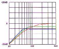
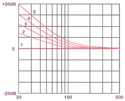
The equalizer range is divided into five low frequency switch positions. Four of them corresponded to the solid angle that the speaker is radiating into. This is 360°(2p), 180°(p), 90°(p/2), and 45°(p/4). The low frequency switch is used as follows: Position 5: When the speaker is away from all surfaces. Position 4: When the speaker is against the wall and away from the floor. Position 3: When the speaker is on the floor against the wall. Position 2: When the speaker is in the corner on the floor. Position 1: is electrically flat. Dual concentric knobs are used for independent equalization on each channel. Separate adjustments can be made, for instance, when one speaker might be located in the corner and the other is not.
![]()
The price that is paid for the outstanding low frequency performance of the ML-1C and equalizer combination is that more power is needed to maintain flat response as the frequency decreases below 200Hz--apparently as much as 20 dB at 20Hz. It really isn't as bad as it looks, however. Compared to a system with a Qts of 1 (blue curve), that's flat down to resonance, the McIntosh woofer has as much as 6dB more output. This means that above approximately 75Hz the power requirements are less for the McIntosh woofer for the same sound level. It's only below 75Hz that efficiency gradually decreases, and is down 14dB at 20Hz.
That's still a little over 11 times the power. In practice, however, the power requirements are demonstrated to have increased very little compared to a system that is flat to 50Hz. Why? Records and music in general don't have that much deep bass output compared to the upper bass and higher frequencies. To verify this I used the Bruel & Kjaer 3347 real time analyzer with the peak hold feature to find some records that have deep bass. Some of the records current at that time are:
|
Star Wars and Close Encounters--London MFSL 1-008 "Close Encounters"-side 2 band 2 |
The Fox Touch--Crystal Clear CCS-7001 "Toccata & Fugue in D minor"-side 2 band 1 |
|
|
Romeo and Juliet--Shefield Lab 8 SL25-SL-26 side 1 |
The Artistry of Diane Bish--Suncoast Concert SCJ 771 "Rigaudon" side 1 band 3 |
|
|
Star Wars and Other Galactic Funk--Millenium MNLP 8001 side 1 |
Fresh Aire Volume 1--American Gramophone AG355 "Pass the Keg" side 1 band 4 |
|
|
Dark Side Of the Moon--Harvest SMAS 11163 "Speak To Me" side 1 band 1 |
Mormon Tabernacle Organ--American Gramophone CADD 1040 "Piece Heroique" side B band 4 |
|
|
Star Wars and Close Encounters London MFSL 1-008 "Cantina Band" side 1 band 4 |
Bottom End Test Record--M&K "Cannon Crescendo from 1812" side 1 band 1 |
Some of these records have substantial output to 32Hz and a few to 25 Hz. Even these selected records have higher output in the upper bass, but of course not always at the same time. Obviously CD's and DVD's did not exist in 1970. However, today's recordings typically still exhibit the same characteristics.
The ML-2C, ML-2M, ML-4C and ML-4M systems are floor models and are normally used against a wall, but can still be placed in or out of a corner. The equalizer settings apply in the same way as for the ML-1. The ML-2's have two 12" woofers and the ML-4's have four woofers. Low frequency distortion is reduced even more with these systems.
When the first Power Guard amplifier (the MC2205 at 200 watts/channel) came out in 1973, it provided added insurance that the power amplifier cannot be overdriven with the bass boost equalizer. In addition, the ML-1C can actually handle program peaks much higher than the conservative 100-watt rating. In 1997, I tested an original woofer and equalizer and found them still able to meet my original specs. I have played the ML-1C's at very high levels using an MC7300 amplifier (300 watts/channel) and CD's as a sound source. The bass is still impressive with no sign of woofer bottoming.
|
A supplementary subwoofer was and still is completely unnecessary. |
The following speaker systems are designed for use with the MQ101 and MQ102 equalizers.
|
ML-1C |
ML-4C |
XR-3 |
XR-7 |
![]()
(Note 1) "Hoffman's Iron law, described by Henry Kloss in the mid 1950's and later turned into exact mathematical form by the engineers Thiele and Small, governs the behaviors of woofers. Essentially, it says that a woofer's efficiency is proportional to the volume of its cabinet and to the cube of its cutoff frequency. For example, suppose you have a woofer whose response is flat down to 40 Hz in a 2.0 cubic foot box. To make its response flat down to 20 Hz, you must either increase the cabinet volume by eight times (to 16 cubic feet) or use 8 times as much amplifier power to achieve the same listening volume. This, in a nutshell, is why flat loudspeaker response down to 20 Hz is rare." Stereo Review July 1992 "All about Subwoofers" by Peter W. Mitchell
![]()
|
|
Response:
20Hz to 20,000Hz |
The ML-1C is listed in the New Products section of Stereo Review April 1971. It is described in detail including the ML-4C and ML-4M. The MQ101 and MQ102 Environmental Equalizers and their function are also described. The original selling price for the ML-1C at that time was $312.00 each. The ML-4C and ML-4M were $1012.00 each.
![]()
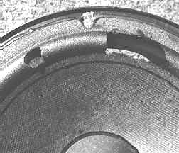 After more than 40 years,
the most common problem is the deterioration of the 12" woofer and some
8" lower-mid surrounds. Only the surrounds need to be replaced. New
drivers or new cone assemblies are not needed or recommended. Surrounds can be
replaced with new polyether ones that will not deteriorate like the original
polyurethane surrounds. Some early 8" mids had coated cloth surrounds that
don't need to be replaced.
After more than 40 years,
the most common problem is the deterioration of the 12" woofer and some
8" lower-mid surrounds. Only the surrounds need to be replaced. New
drivers or new cone assemblies are not needed or recommended. Surrounds can be
replaced with new polyether ones that will not deteriorate like the original
polyurethane surrounds. Some early 8" mids had coated cloth surrounds that
don't need to be replaced.
Be certain the new woofer surrounds are made of polyether and that they have a 3/4" diameter roll. Many speaker repair centers do not supply the larger 3/4" roll. A surround that has only a 1/2" roll will restrict the woofer excursion and cause distortion for deep bass notes. If you have new surrounds put on the woofer for you, be certain they are NOT the rubber types. These heavy surrounds reduce the efficiency of the woofer and it will no longer match the 8" lower mid-range output. The heavy surround will also alter the woofer response and it will no longer match the MQ101 or MQ102 equalizer compensation required for the system to provide flat response to 20 Hz.
The new 8" surround must also be polyether and the roll must be 1/2" in diameter. The 12" and 8" surrounds can be replaced with do-it-yourself kits or you can have them replaced for you by a McIntosh dealer or suppliers such as Newfoam.
![]()
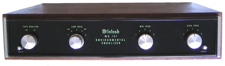
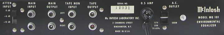
The MQ101 Environmental Equalizer
The MQ101 Environmental Equalizer has an illuminated glass panel that matches the appearance and width of other McIntosh electronics. It also has Panloc fasteners that allow it to be locked in place in the cabinet or it can be unlocked to slide out. It is shipped complete with a wood cabinet. It can also be custom mounted using the panloc brackets from the cabinet. There is no power switch in the MQ101. It can be plugged to a switched outlet in the preamplifier or receiver.
The MQ101 also has mid and high frequency controls. Some speaker systems have controls for the mid and tweeter that are part of the crossover network. These controls or switches are located at the rear of the cabinet that require reaching behind each speaker to make an adjustment. In addition, the potentiometers or switches that are used often become intermittent. The speaker system impedance also changes with various settings, sometimes going too low. In addition, the frequency range covered by each control is limited by the frequency range and efficiency of the mid or tweeter in the system.
In comparison, the MQ101 mid frequency and high frequency controls can be remotely adjusted, do not affect the impedance, and avoid high currents. The frequency band for the mid and high frequencies is not limited to only the frequency range or efficiency of the mid or tweeter. It covers a range that relates better to music.
The input to the MQ101 normally comes from the preamplifier main output. The output from the MQ101 then goes to the power amplifier input. However, when used with a receiver, access to the preamp output and power amp input is not always available. A way around this is to use the tape monitor section of the receiver. Tape Out from the receiver goes to the MQ101 input and the MQ101 output goes to Tape In on the receiver. The tape monitor switch in the receiver must then be left at the IN position. The Tape monitor function in the receiver is, of course, lost. A tape monitor switch on the front panel of the MQ101 is provided to restore this feature. Input and output jacks are located at the rear of the MQ101.
When The MQ101 is used with the tape monitor circuit, this would be equivalent to driving the MQ101 with the volume of the preamplifier up full. The MQ101 can then be overdriven. A three position input attenuator slide switch is at the left side in the rear. It is normally used in the 0dB position but when the MQ101 is driven by the tape monitor output, the switch must be placed in the –12dB position.
Response: 20Hz to
20,000Hz (+0.5 -0.5dB)
Distortion: 0.1%
Hum and noise: -80dB
Input sensitivity: 2.5V
Input impedance: 60k ohms
Input attenuator switch: 0dB, -6dB and -12dB
Output: 2.5V into 47k ohms
Tape monitor: inputs and outputs with switch
Equalization low frequency: 0 to +17dB at 20Hz in 5 steps (0, +6, +9, +13 and
+17dB)
Equalization mid frequency: -5 to +5dB at 4000Hz in 5 equal steps
Equalization high frequency: -4 to +4dB at 20kHz in 5 equal steps
Front panel: illuminated gold/teal with Panloc mounting
Size: 2-15/16" high, 16" wide and 10" deep (1-1/2" knob
clearance)
Cabinet size: 3-1/2" high, 16-5/8" wide and 9-3/8" deep
Weight: 15 lb.
Sold from: 1970-1978
Last retail price: $250.00 (cabinet included)
An MQ101 Owner’s Manual can be found on a separate page.
![]()
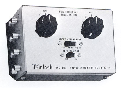
Shortly after the ML-1C and MQ101 went into production, the MQ102 was introduced. This lower cost equalizer provides the same low frequency compensation as the MQ101 but has a none of the extra features except the tape monitor function. The box is black and chrome with black silk-screened lettering on the chrome. The left and right channel low frequency equalization controls are near the top of the picture. Each is selectable for positions 1 through 5. There is no power switch in the MQ102. It can be plugged to a switched outlet in the preamplifier or receiver.
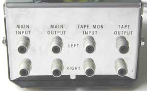 The input to the MQ102
normally comes from the preamplifier main output. The output from the MQ102
then goes to the power amplifier input. However, when used with a receiver,
access to the preamp output and power amp input is not always available. A way
around this is to use the tape monitor section of the receiver. Tape Out from
the receiver goes to the MQ102 input and the MQ102 output goes to Tape In on the
receiver. The tape monitor switch in the receiver must then be left at the IN
position. The Tape monitor function in the receiver is, of course, lost. A tape
monitor switch on the side of the MQ102 is provided to restore this feature.
Input and output jacks are located on the side of the MQ102.
The input to the MQ102
normally comes from the preamplifier main output. The output from the MQ102
then goes to the power amplifier input. However, when used with a receiver,
access to the preamp output and power amp input is not always available. A way
around this is to use the tape monitor section of the receiver. Tape Out from
the receiver goes to the MQ102 input and the MQ102 output goes to Tape In on the
receiver. The tape monitor switch in the receiver must then be left at the IN
position. The Tape monitor function in the receiver is, of course, lost. A tape
monitor switch on the side of the MQ102 is provided to restore this feature.
Input and output jacks are located on the side of the MQ102.
When The MQ102 is used with the tape monitor circuit, this would be equivalent to driving the MQ102 with the volume of the preamplifier up full. The MQ102 can then be overdriven. A three position input attenuator slide switch is at the top of the box at the center. It is normally used in the 0dB position but when the MQ102 is driven with the tape monitor output, the switch must be placed in the –12dB position.
Response: 20Hz to
20,000Hz +/- 0.5dB
Distortion: Will not exceed 0.1% at rated output from 20Hz to 20kHz,
Hum and noise: -80dB below rated output
Input sensitivity: 2.5V
Input impedance: 60k ohms
Input attenuator switch: 0dB, -6dB and -12dB
Output: 2.5V into 47k ohms or more
Tape monitor: inputs and outputs with switch
Equalization: 0 to +17dB at 20Hz in 5 steps (0, +6, +9, +13 and +17dB) in
positions 1, 2, 3, 4, and 5 respectively.
Finish: Black and chrome
Size: 2-1/2" high, 6-3/4" wide and 4-1/8" deep. Knob clearance
1-1/2"
Weight: 2-1/2 lb.
Sold from: 1970-1978
Last retail price: $74.50
![]()
Number 3,721,861 assigned to Sidney A. Corderman at McIntosh Laboratory. This patent contains mostly background material of my speaker-equalizer design including a diagram of the ML-4 crossover, MQ101 circuitry and response curves. The actual patent is for a protective circuit used in the MQ101. It consists of a reed relay and RC timing circuit that shorts the equalizer output for about 1 second and prevents turn-on transients from being sent to a power amplifier.
Number 3,803,359 assigned to Sidney A. Corderman at McIntosh Laboratory. This patent contains more background material of my speaker-equalizer design including details of the ML-1C operation, a diagram of the ML-4 crossover, MQ101 circuitry and response curves. The actual patent is for the cascading of the three low, mid and high frequency contours in the equalizer.
![]()
Although my 1973 patent is for equalization of an overdamped woofer, the equalizer includes compensation for different radiation angles but is not part of the patent. In 1975, Acoustic Research came out with the AR-10pi speaker system that has a similar stepped compensation. The equalization is accomplished not with a separate active equalizer like the MQ101 but with passive crossover network elements and a transformer inside the speaker enclosure. A flip down panel on the front of the AR-10pi covers three switches for adjusting the response. I had the opportunity to test the 10pi at that time. Unfortunately the transformer in the enclosure goes into saturation at frequencies approaching 20 Hz, causing significant distortion beyond that generated by the woofer. The system efficiency is a little below 85 dB compared to 89 dB for the ML-1C (above 200Hz). The 10pi was reviewed in High Fidelity magazine in July 1977. It sold for $425.00 and the ML-1C sold for $399.00.
My patent was cited as a reference in the AR patent for the 10pi. The patent, number 4,021,614 Woofer Equalizer, was awarded to John Bubbers on May 3, 1977 and assigned to Teledyne, Inc. AR was owned by Teledyne at that time. A patent search shows this to be his only patent. I remember that in a conversation, when visiting with John Bubbers in October, 1973, I had told John about my equalizer and features. Of course, it was no secret then because it was in production. Perhaps he decided to patent the part of the equalizer that wasn't covered by my patent.
Further, I have found mention of this from an article in the October 1957 issue of Audio magazine. This is by Ed Villchur at Acoustic Research titled Loudspeaker Damping. He mentions the effect of solid angle seen by the speaker: "It would seem to be a good idea for someone to design an equalizer network to provide variable bass boost to compensate for this effect on performance due to change in solid angle." No patent had been filed. The behavior of speaker radiation into various solid angles is common knowledge. It is explained in detail in books such as Acoustics by Leo Beranek published in 1954 and Hi-Fi Loudspeakers and Enclosures by Abraham Cohen published in 1956. While at the Sonotone Corporation, I spent the day once in the early 1960's with Abe and ran response curves for him on his Bi-phonic Coupler speaker system.
AR further pursued the idea of electronic bass equalization. The patent number 4,113,983 Input Filtering Apparatus For Loudspeakers was issued to Paul Steel on September 12, 1978 and assigned to Teledyne Acoustic Research. It describes a bass boost system but with a feedback circuit to limit the low frequency power delivered to woofer. This prevents bottoming of the woofer cone, spider or voice coil. The greater the power to the woofer at the lowest frequencies, the higher the cutoff frequency for the low end of the woofer. The net effect is to limit deep bass from being reproduced at loud levels.
In my opinion neither of these ideas patented by Acoustic Research will reproduce the lowest frequencies as accurately as the ML-1C and MQ101 combination. When the MQ101 is used, there is no significant distortion introduced by its use and there is no need for gimmicks to restrict the bass response right where it is needed and wanted for accurate reproduction.
In 1972 the Concept EQ-5 was introduced by University Sound Division of LTV Altec. According to advertising, this system has a 12-inch overdamped woofer. The equalizer reportedly restores flat bass response and permits contouring of other portions of the audio spectrum to suit the acoustics of individual listening rooms. Three contouring controls are provided: low frequency (-6 dB to flat response in three steps); mid bass (-6 to +6 dB) in five steps); high frequency (-6 to flat response in three steps). The system also has a 5-inch mid-range and a small dome tweeter. The two speakers and equalizer sold for $399.00.
Although this appears to be a copy of my patents, Gordon Gow felt this was not worth pursuing and the system was apparently discontinued soon after it was introduced. The idea was undoubtedly brought to the attention of Altec by Dale, who worked for me for a short time and learned about the theory. After leaving McIntosh, he went to work for Altec. No patents for this system were applied for. Later, Dale was awarded two design patents at Altec for speaker appearance.
In 1979, KLH announced the KLH-3. This system uses an active analog bass “computer” (equalizer) in a separate cabinet. It essentially extends the bass down to 40 Hz but limits the woofer excursion if the amplitude of the low frequency program material becomes too great. The novelty is that the extended bass is accomplished in a speaker cabinet only 8” X 12” X 6”. The pair of speakers and equalizer sold for $450.00. Again, this is a much compromised attempt to extend low frequency response. The system was discontinued soon after.
![]()
|
The Equalizer History is divided into four parts |
|
|
The ML-1C
Speaker, MQ101 and MQ102 Equalizers |
|
![]()
|
About This Site |
||
|
More text and pictures about McIntosh will be added as my research continues. Any comments, corrections, or additions are welcome. |
||
|
All contents are copyrighted |
||