Equalizers
By Roger Russell
These pages are copyrighted.
No portion of this site may be reproduced in whole or in part
without written permission of the author.
What is on This Page?
What is an equalizer? In the old movies, an equalizer was known as something that could make any person equal to the biggest and the toughest of the best. Edward G. Robinson and Humphrey Bogart could become really tough guys on the screen. When they pulled out their equalizer, they got everyone’s attention and people did what they were told to do, or else!
![]()
In audio, Equalization is used in almost every component in your system in one way or another. Sometimes the words used to describe the process are different but the principle is the same—to overcome obstacles that make the system work better. Response can be tailored to accomplish a specific task with a certain shape and amplitude. Equalization is used in the recording consoles. It is used in preamplifiers for magnetic cartridges, for tone controls and loudness contours. It is used in an FM tuner as a de-emphasis network for the correct response. The Dolby system uses equalization and so on and so on. In acoustics, there are equalizers that work with a speaker system to achieve a specific acoustic output. There are equalizers that compensate for different speaker locations in a room and even equalizers that compensate for response peaks and dips due to room resonances.
However, when it comes to the insertion of an external component into a system, such as an equalizer, this could supposedly cause concern for some people because it takes up space and could promote fear that it might add distortion or noise to the system. They may also be influenced by those who are unburdened with knowledge that this could be a bad thing. Perhaps, if it was built-into the amplifier or preamplifier, then it would be accepted like tone controls or a loudness control.
Is “equalizer” a bad word? Equalizers are given different names to avoid that term. They are also known as a “compensator.” An exotic terminology called a “sixth order Butterworth filter” is used by Electro-Voice for their Interface equalizer? In the Bose 2201 system, equalization is termed as a “spectral matching network.” In the final analysis an equalizer by any other name is still an equalizer.
![]()
Patent number 1,984,450 Compensated Amplifier was awarded to Julius G. Aceves, New York, NY on December 18, 1934. Application number 513,061 was issued on February 3, 1931. The introduction is as follows:
“This invention relates to compensated amplifiers and has for an object, to selectively control the gain of an amplifier for different frequencies. The invention is of particular utility for controlling tone in recording and reproducing sounds and other objects of the invention are to reinforce certain desirable frequencies which, under ordinary circumstances, are more or less lost and subdue other undesirable frequencies. According to the invention, provision is made for transmitting the low frequencies and the high frequencies with greater voltage amplification than the intermediate frequencies, thereby making it possible to selectively amplify the different registers faithfully to produce vocal or instrumental sounds. In particular, the invention aims to effect reinforcement of the bass tones in the range below 100 cycles per second and to reinforce the treble tones above the 1,000 cycles per second. Also, in connection with phonograph pickup devices, the invention aims to eliminate the so-called scratch or surface noise and to reduce or eliminate the effect of cabinet or loudspeaker resonance. The invention may be embodied in a compensator to be used ahead of an amplifier or may be embodied in an amplifier as an integral part thereof. With either embodiment, selective control of the low, intermediate and high registers is provided by means of which the amplification of the various registers may be differentially effected.”
![]()
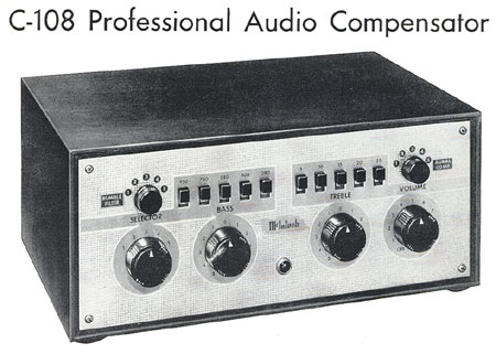
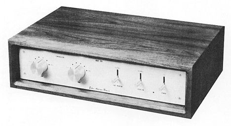
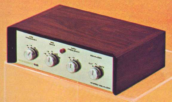
McIntosh C-108 Professional Audio Compensator
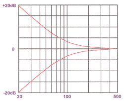
Then there are equalizers needed to play records. Back in the 50’s, there were so many different kinds of playback curves needed for various records, such as LP, AES, etc. that a combination of switches could be selected in the McIntosh C-108 preamplifier to provide the correct playback for each one. The term compensation was used instead of equalization but the results were the same. It was many years later that a single standard was established as the RIAA curve. To this day records are still held in high esteem by many despite the fact that equalization is essential to record and play back these records. In fact, 42.5 dB of equalization is needed to properly play a record with a magnetic pickup and that is more than any speaker ever needed. Tape heads also need similar equalization.
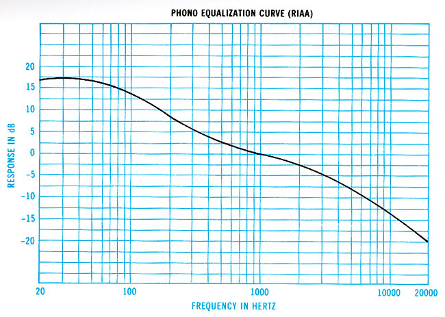
This RIAA equalization curve is what is now commonly in use.
![]()
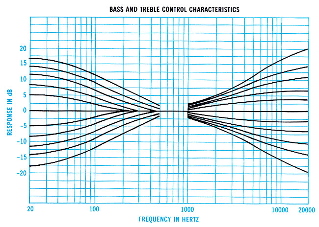
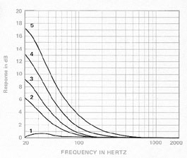
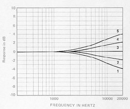
Above are typical program control curves that were called tone controls. They have been used for many years and some stereo equipment designs still incorporate them. Some were switch controlled in steps as shown above and others were continuously variable. They all centered at about 1kHz. Maximum boost or cut was as much as 20 dB. Using the controls at full maximum could cause an amplifier or speaker to be overdriven.
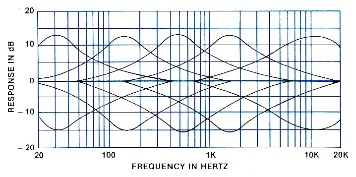
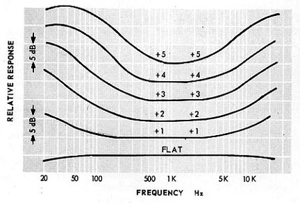
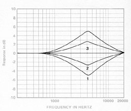
In 1976, I redesigned the tone control curves for McIntosh to better conform to actual program material. I decided to base the new "program controls" on a suggestion by the famous conductor Leopold Stokowski. Mr. Stokowski was a member of the Audio Engineering Society. In a paper presented many years ago, he suggested that the frequency range could be divided into five bands. Although the exact center frequencies were not specified, there was the lower bass, upper bass, lower mid-range, upper mid-range and highs. I had made many spectrum measurements from several different live sources. This included voice, several musical instruments in the lab and The Binghamton Symphony concerts. I also analyzed a wide variety of classical and rock recordings using Bruel & Kjaer equipment that read averages or peaks using octave and 1/3 octave filters.
With this information and my listening experience, I arrived at the center frequencies of 30, 150, 500, 1500 and 10,000 Hz. The 10 kHz curve was different in that it covered a wide range from 1500Hz to 20kHz. High frequencies are often thought of as something that is only handled by the tweeter. However, in the terms of music, "highs" extend down much lower. The amount of boost and cut is reduced to only 12dB instead of 20 dB used in earlier equipment. The controls are continuously variable.
I also specified a set of simplified, and perhaps slightly compromised, three-band controls for other equipment. The center frequencies are 30, 750 and 10,000Hz. Boost and cut remain at 12dB. They were still very effective for lower cost products.
Although the 5-band and 3-band designs were specifically for program material, they were inadvertently given the general name of equalizer controls, making their use misleading.
![]()
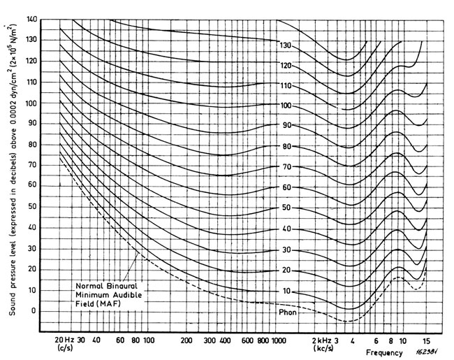
Unlike many test signals and test equipment used today, the ear responds very differently. For instance: the Fletcher-Munson curves shown above are of perceived equal loudness. What this says is that the ear is much less sensitive to lower frequencies at lower levels. One good reason is that if you have ever tried to make a recording outdoors on a windy day, the wind noise will easily overdrive the recorder because the microphone responds to low frequencies at low levels—something we barely hear and again, benefits our survival. If you were to imagine the curves turned upside down, they indicate that the most sensitive area of hearing at lower levels is in the range of about 400 to 8000 Hz and is greatest in the 3000 to 4500 Hz range.
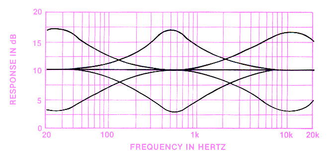
Shown above is loudness compensation that is used in a preamplifier. In this particular preamp, there are two listening level controls, one for volume and one for loudness. Typically, the loudness control is set to zero %. The volume control is advanced to the loudest setting that would ever be used. The loudness control can then be advanced to reduce listening to a preferred level. At the same time the lows and highs are increased to produce the same apparent sound that would normally be heard at higher listening levels. Many pieces of equipment do not have a separate continuously variable control. Instead, a switch is used to provide a fixed amount of compensation regardless of the listening level.
![]()
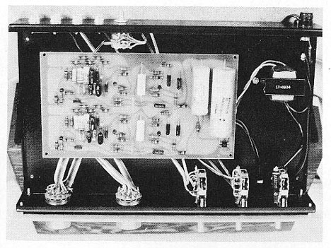
Elektra Amplidyne SE-III Stereo Loudspeaker Equalizer
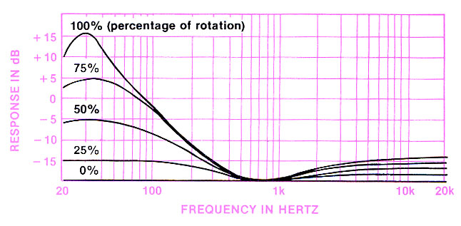
Although this device is dubbed “loudspeaker equalizer”, the performance is very much like typical tone controls. This might enhance the sound of a few loudspeakers but it is not designed to complement any particular speaker. It isn’t even useful for loudness compensation because the high frequency boost is excessive. It was reviewed in the June 1970 issue of Audio magazine.
High Control: flat and five high-frequency equalization settings.
Low Control: flat and five low-frequency equalization settings.
Switches: Power, Equalization in-out, Tape monitor in-out
Level Control: Adjustable—located on rear panel.
Dimensions: 15” wide, 3” high and 10-3/8” deep.
Weight: 15 lbs, including oiled walnut cabinet.
Price: $129.95
![]()
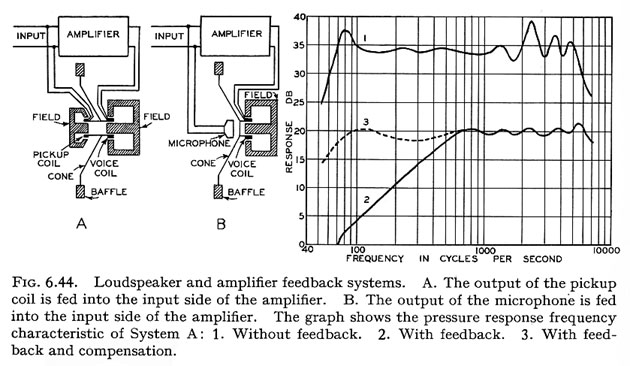
Attempts to correct the response of a loudspeaker go way back in time. It can be accomplished in several different ways, electrically, mechanically or acoustically. A novel way described by Dr. Harry Olson in his 1957 book Acoustical Engineering, page 168, is to use feedback and is shown above. It can be the output of a sensor such as a pickup coil or microphone and used as a correcting signal fed back to the power amplifier. Note that curve 3 includes not only feedback but also the term called compensation.
Mechanical and Acoustic Equalizers
Other electrical equalization can be used such as a crossover network to correct driver response. This can include a mid-band correction such as an RLC circuit connected in series or shunt. It can also be used to get rid of an impedance peak (zobel).
Mechanical enhancements can be used in various cone materials and cone shapes to correct response. Concentric rings of thicker cone material helped to smooth response. Various supplementary materials can also be applied to the cone such as foam , aluminum, etc. The surrounds can also be made of various materials and shapes. Is this a method of equalization to make response more uniform?
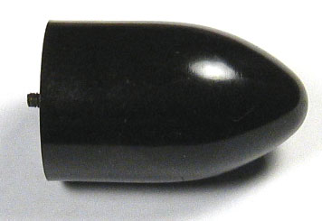
Lowther Stabilizer (equalizer)
For acoustic enhancements, various internal cabinet divisions, vents and acoustic materials can be manipulated to correct or extend response, particularly at the lower frequencies. Sometimes diffusers, such as those used in the University Sphericon tweeter or the Lowther plastic phasing plug, were employed. The above photo was called a stabilizer or phasing plug and was used in the Lowther PM4 driver that I purchased in 1959. The idea here was to attach this to the pole piece with the threaded rod at the left. When used in conjunction with a concentric conical cone, known as a whizzer, it formed a horn loading between the plug and the whizzer and extended the high frequency response.
McIntosh Dome Mid-Range
In the McIntosh 036 mid-range dome, a fiberglass washer and small aluminum disc in front of the dome were used to adjust the response for a specific frequency range and also to smooth it out. You can call this acoustic equalization.
![]()
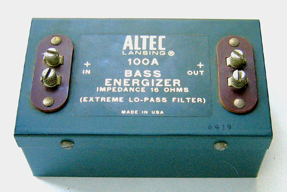
This is a passive equalizer and operates as a low-pass filter. It is connected between the power amplifier output and the speaker terminals. Although it was designed for use with a 16-ohm system, it could also be used with an 8-ohm system. The term energizer is another of those words that means equalizer. In this design, the frequencies above 150 Hz are attenuated by 6 dB and attenuation gradually decreases as frequency decreases below 150 Hz, giving the effect of a bass boost to the speaker. However, the penalty is that the system must be driven with 4 times the power for the same listening level in the rest of the frequency range. This characteristic is also known s insertion loss.
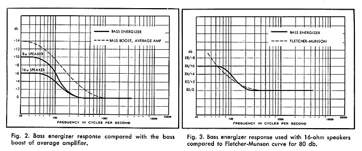
If the energizer is used with an 8-ohm system, there is a 10 dB insertion loss. In this case, 10 times the power is needed for the same listening level through most of the range. In either case, when it comes to increasing the bass output by driving the speaker with up to 10 times the power at the lowest frequencies, extra demands are placed on the power amplifier to supply sufficient power and could be driven into clipping. This, in turn, could damage the speaker. For instance, if you normally listen at a maximum of 10 watts peak, you would now need a 100 watt amplifier.
All of this is well and good if the energizer is designed for a specific loudspeaker system that is designed to handle this much low frequency power. However, the bass Energizer is said to be used with any “small” speaker system and some systems may not be able to handle that much low frequency power, resulting in woofer damage or burnout.
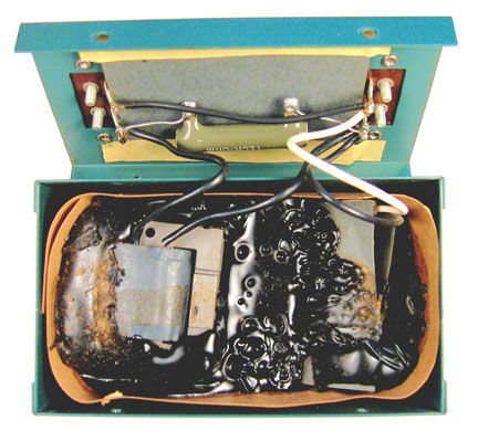
The internal components are held in place with a tar potting material. The circuit consists of a series coil with a laminated core. It is connected in series between the input and output. A 15-ohm power resistor is connected across the coil. This serves to limit the amount of boost. A 150 mfd capacitor is connected across the output terminals resulting in a 12 dB per octave crossover.
An article was published in Audio Magazine, June, 1965 by Bill Yeager and Roger Hull titled “Bass Transfusion for Little Speakers.” This article describes the Bass Energizer and how it can extend the bass response for a loudspeaker system. Although an example of a small speaker in the article is an 8” woofer, today a small speaker can be as small as 4” with even less power handling ability.
![]()
Courtesy of Rodriguez
![]()
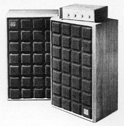
McIntosh ML-1C and MQ101 Equalizer
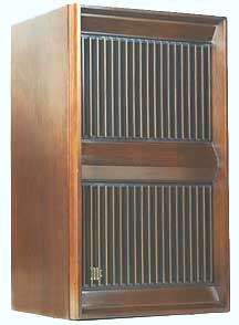
McIntosh ML-1C
The McIntosh Environmental Equalizers all began with my first patent number 3,715,501 "Loudspeaker System". It consists of a loudspeaker and equalizer that forms the complete system.. No subwoofer is needed! The system works just as well today as it did in 1970. The combination extends response flat from 150Hz down to 20Hz within 1 dB. The system was introduced in 1971.
 The ultimate slope of the low frequency rolloff for
all sealed systems is 12dB/octave. As a system becomes more underdamped, there
is a greater tendency for it to ring. It means the cone motion does not stop
when the signal stops. It keeps on moving and gradually decays. Critical or
overdamped systems have no tendency to ring. The overdamped approach is not
normally a good design because it has relatively few low frequencies compared
to the upper bass. This was where the equalizer came into being. I created an
electrical equalization circuit that was just the opposite of the overdamped
woofer rolloff. Wherever the response was down, the equalizer was up by an
equal amount, effectively maintaining a flat response for the speaker and
equalizer combination. What was nice about this concept was that the
equalization continued to correct for response right through the system
resonance of about 50 Hz and right on down to 20Hz and below. Electronic
equalization was made prior to the power amplifier so there were no losses or
load impedance problems introduced between the power amplifier and the speaker.
The ultimate slope of the low frequency rolloff for
all sealed systems is 12dB/octave. As a system becomes more underdamped, there
is a greater tendency for it to ring. It means the cone motion does not stop
when the signal stops. It keeps on moving and gradually decays. Critical or
overdamped systems have no tendency to ring. The overdamped approach is not
normally a good design because it has relatively few low frequencies compared
to the upper bass. This was where the equalizer came into being. I created an
electrical equalization circuit that was just the opposite of the overdamped
woofer rolloff. Wherever the response was down, the equalizer was up by an
equal amount, effectively maintaining a flat response for the speaker and
equalizer combination. What was nice about this concept was that the
equalization continued to correct for response right through the system
resonance of about 50 Hz and right on down to 20Hz and below. Electronic
equalization was made prior to the power amplifier so there were no losses or
load impedance problems introduced between the power amplifier and the speaker.
McIntosh MQ101 Environmental Equalizer
I chose 20Hz as the limit and began to roll off frequencies below there. There were several reasons for this. At the time there was turntable rumble, record rumble and tonearm resonance. There was also the cone excursion limit to be considered. Each octave lower means four times the cone excursion. Even though the equalizer was rolled off below 20Hz, it didn’t just suddenly die. There was still some response even at 10Hz but the acoustic output just wasn't flat any more. Today, where CD's and other means of recording are no longer plagued by rumble, arm resonances etc., flat response could be extended down even further. Of course, the woofer must still not be overdriven.
|
|
|
|
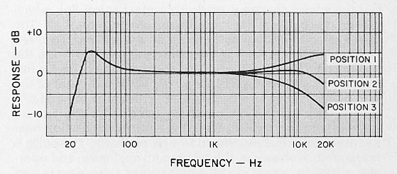
I cited the Aceves patent for low frequency equalization in my patent. However, my equalizer went a step further. It not only compensates for the low frequency driver but is combined to compensate for the radiation angle into the room. It is divided into five low frequency switch positions. Four of them correspond to the solid angle that the speaker is radiating into. This is 360°(2p), 180°(p), 90°(p/2), and 45°(p/4). The low frequency switch is used as follows: Position 5: When the speaker is away from all surfaces. Position 4: When the speaker is against the wall and away from the floor. Position 3: When the speaker is on the floor against the wall. Position 2: When the speaker is in the corner on the floor. Position 1: is electrically flat. Dual concentric knobs are used for independent equalization on each channel. Separate adjustments can be made, for instance, when one speaker might be located in the corner and the other is not.
The MQ101 also has mid and high frequency controls. Some speaker systems have controls for the mid and tweeter that are part of the crossover network. These controls or switches are located at the rear of the cabinet that requires reaching behind each speaker to make an adjustment. In addition, the potentiometers or switches that are used often become intermittent. The speaker system impedance also changes with various settings, sometimes going too low. In addition, the frequency range covered by each control is limited by the frequency range and efficiency of the mid or tweeter in the system.
In comparison, the MQ101 mid frequency and high frequency controls can be remotely adjusted, do not affect the impedance, and avoid high currents. The frequency band for the mid and high frequencies is not limited to only the frequency range or efficiency of the mid or tweeter. It covers a range that relates better to music.
Room equalization
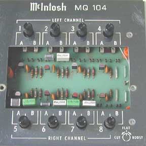
In addition to compensating for McIntosh loudspeaker response and the position of the speaker in the room, a third factor affecting the sound is room resonance. Multiple resonances are determined by room dimensions and construction. The McIntosh MQ104 can provide all three compensations. Four adjustable filters per channel can be used to compensate for room resonances. The frequency, bandwidth and amplitude can be adjusted to smooth response in the listening area. Acoustic Measurement is required to properly set the filters.
More detailed information about the McIntosh equalizers.
|
The McIntosh Equalizer History is divided into four parts |
|
|
The ML-1C Speaker, MQ101 and MQ102
Equalizers |
|
![]()
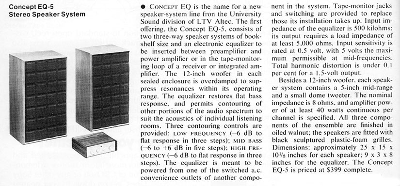
Altec Concept EQ Stereo Speakers and Equalizer
After the introduction of my integrated ML-1C speaker/equalizer system and patent in 1971, a few other companies came out with their version of my design. The Altec Lansing Concept EQ speaker/equalizer system was introduced in 1972 after a person, who worked for me for a short time, left for Altec and undoubtedly inspired them with my work and patent.
The Concept EQ was advertised once in the September and November1973 issues of Audio magazine and once in the August 1973 Stereo Review magazine. It was also mentioned in an article in the November 1973 issue of Audio titled “Equalization in the Home” by John Eargle, who worked at Altec Lansing. It was discontinued soon after.
The system originally sold for $360 for the pair of speakers
The equalizer could be purchased separately at a cost of $125.00
The speaker system consisted of a 12” woofer, 5” mid-range and 2” dome tweeter. Power handling was 100 watts. Crossover frequencies were at 800Hz and 8Khz. Impedance was 8-ohms. Dimensions were 15”w, 10-5/8”d and 25”h. Weight was 38 lbs. Finish was walnut and the grille was sculptured urethane foam.
Concept EQ Equalizer
Controls:
Low frequency: -6, -3, 0
Mid Bass: -6, -3, 0 +3, +6,
High frequency: -6, -3, 0
Equalization: Out, in, tape
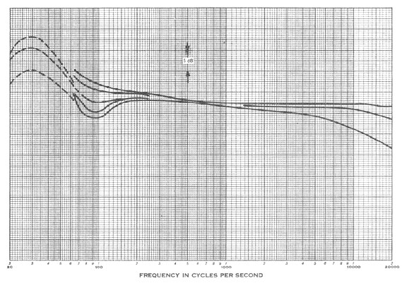
Equalizer Response
The EQ equalizer is claimed to suppress the 80 to 150 Hz area that was alleged to be commonly found in rooms in the home. Claims were also made that this equalizer, despite the blanket attempt to correct response for a few rooms, did not correct accurately for a wide range of possible room resonances that could be as low as 20 Hz or as high as 1000 Hz. Unfortunately, each room has its own unique acoustic resonances and the McIntosh MQ 104 equalizer introduced in 1973 provided adjustable frequency and amplitude filters to accurately correct for specific resonances found in homes.
It was also claimed to be a welcome adjunct to most wide-range systems. However, boosting low frequencies to just any system could easily overdrive the speaker and cause damage. It could also cause the amplifier to go into clipping at low frequencies causing distortion and possible damage to the drivers.
This description was in the new products section of the June 1972 issue of Stereo Review magazine.
![]()
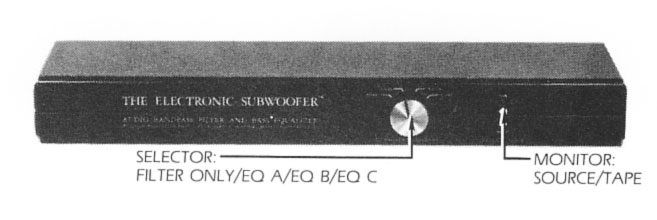
Another late comer is the Allison equalizer sold from 1979 to 1982 at a price of $290.00. It compensates for the low frequency rolloff of a sealed system below the system resonant frequency. Low frequency boost is at the rate of 12 dB per octave. The equalization switch positions are mainly for the Allison speakers. The A35.5 position is for models One and Three; the B41 position is for models Two and Four and position C48 is for the model Six. When using this equalizer, response is claimed to be flat to 20 Hz. In addition, the equalizer is claimed to be useful with some other sealed systems. The curves below are from the Allison literature.
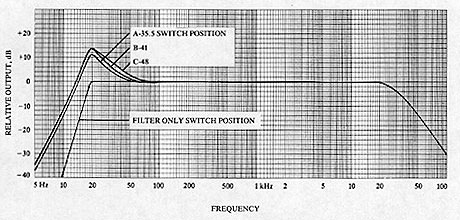
However, because of the 11 to 14 dB increase in power to the speaker, it is not recommended for systems that cannot handle it. High Fidelity magazine is quoted as saying that “Nor can you expect the Allison to make a monitor out of a mini; unless the speaker has quality to start with--in particular, an ability to handle 10 to 14 dB of added signal at 20 Hz without distress—the Electronic Subwoofer is, frankly, a waste of money. But, in conjunction with a capable speaker, we find that its benefits grow on you. The longer we use it, the less willing we are to forego it. The measurements below are from a review of the Allison Electronic Subwoofer in High Fidelity Magazine, October 1979.
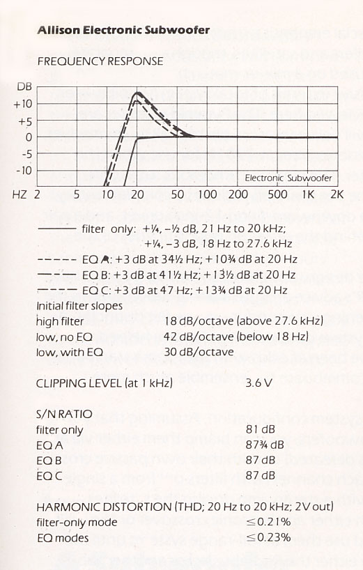
The Allison is very similar to the McIntosh equalizer that came out several years earlier. The McIntosh equalizer is used with a McIntosh-designed woofer that can handle up to 20 dB in signal increase at 20 Hz. The extra- long high-power voice coil of the woofer in conjunction with the machined out back plate to allow extra long excursions offers an exceptional performance. The McIntosh equalizer extends response flat to 20 Hz. Due to its unique equalization, the McIntosh equalizer is not recommended to use with other speakers. A tape monitor insertion feature was used in the McIntosh equalizer and Allison had also included this in their equalizer.
![]()
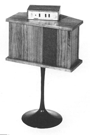
EV Interface A
About 1974, Electro-Voice (EV) came out with their version of an equalized speaker called the Interface A. The walnut cabinets are 22” high, 14” wide and 7-3/4” deep. The equalizer is 8” wide, 2-3/4” high and 6-1/4” deep. The woofer is 8” in diameter and a 12” a weighted passive radiator is used to extend the bass along with the equalizer. A front-mounted cone tweeter is covered with a thin piece of felt with a hole in the center. Another tweeter is mounted at the rear of the enclosure. The original price for the two speakers plus the equalizer was $400.
The system was reviewed by Consumer reports in February, 1974 and by Audio magazine in March 1976. Instead of using the term “equalizer,” a more scientific name was used called a “sixth order Butterworth filter.” However, it boosted the bass response of the system as other equalizers did.
The above equalizer curve shows that only a moderate amount of bass boost was used. EV claimed that less amplifier power was used but then measurements by Consumer Union show the response, even with the equalizer, began to roll off below about 80 Hz. EV literature pointed out that some equalizers require up o 20 dB or 100 times the power at low frequencies. Of course, they were referring to the McIntosh equalizer that extended the response to 20 Hz. In practice, the power demands for most program material with the McIntosh equalizer were about the same as non-equalized systems. It was only for deep bass such as low frequency organ notes that more power was needed. This was not a problem for the McIntosh system. The woofer was designed to handle the power with low distortion and, conveniently, McIntosh made big amplifiers. The MC2105 had just been introduced and would deliver 100 watts per channel.
The equalizer has a three-position switch for high frequencies and a tape monitor switch for use with receivers and the like where the equalizer could not otherwise be inserted in series between the preamp and power amplifier sections.
Later, the Interface B was introduced and was reduced in price to $350. The enclosure was laminated vinyl and the passive radiator was reduced to 10” in diameter. However, they claimed the efficiency was higher by 3 dB.
EV Sentry III
|
|
|
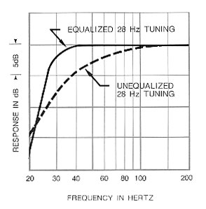
The much larger and more expensive EV Sentry III also used an equalizer to extend the bass frequencies. This system is 28” wide, 36” high and 20-1/2” deep and weighs 156 lbs. It is horn loaded and vented with much higher efficiency than the Interface systems. Equalization for this system extends response to 28 Hz at 3 dB down.
![]()
Bose 2201 system
In December 1, 1959, Amar G. Bose received a patent number 2,915,588 titled Pressure Wave Generation. This was described as a radiating surface of a sphere, 1/2 sphere, 1/4 sphere or 1/8 sphere. The radiating surface was to be composed of many small closely-spaced drivers in a sealed enclosure. It also describes a compensation network which boosts the high and low frequency ends of the spectrum to compensate for the fall off in response of the individual loudspeakers at these ends. Bose cited the Aceves patent mentioned above.
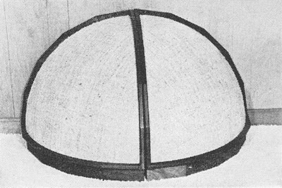
On June 12, 1962, Bose was awarded a second patent number 3,038,964 that further defines the spherical surface concept. The preferred placement is for one section in each corner of the room on the floor. The system was reviewed in High Fidelity magazine, January 1967. It shows an alternate placement, above, by putting the two eighth spheres together to form a quarter of a sphere and placed on the floor against the wall. Each section contains 22 five-inch drivers mounted in a triangular shaped convex baffle which is framed in walnut and faced with grille covering. The enclosure is completely sealed. Inside is a self-powered 50 watt solid-state basic amplifier that drives the speakers and which itself is fed from a spectral circuit known as a “spectral matching network” (in other words, an equalizer circuit, shown below). Of course, placing the system, or any other system, in the corner on the floor provides a higher bass output.

Bose 901 System
 The 901 system is an
arrangement of eight 4-inch drivers that are all closely spaced and facing the
rear wall. The ninth 4-inch driver faces forward. The walnut cabinet is 12-3/4”
high and 20-9/16” wide. The top forms a “V: of 120 degrees. The equalizer has a
power switch, tape monitor switch, low cut filter for frequencies below 40 Hz
and a 5-position high frequency switch. The recommended spacing of the apex of
the cabinet rear to the wall is 12 inches.
The 901 system is an
arrangement of eight 4-inch drivers that are all closely spaced and facing the
rear wall. The ninth 4-inch driver faces forward. The walnut cabinet is 12-3/4”
high and 20-9/16” wide. The top forms a “V: of 120 degrees. The equalizer has a
power switch, tape monitor switch, low cut filter for frequencies below 40 Hz
and a 5-position high frequency switch. The recommended spacing of the apex of
the cabinet rear to the wall is 12 inches.
 The principle of the 901
is based on reflected sound because that is what you mostly hear in a concert hall,
although a living room is not like a concert hall. Bose also claims that
conventional speakers cannot have flat power radiation. This can be easily
disproved. Emphasis for the design principal of the 901 is based on flat power
radiation into the room rather than flat frequency response on axis.
The principle of the 901
is based on reflected sound because that is what you mostly hear in a concert hall,
although a living room is not like a concert hall. Bose also claims that
conventional speakers cannot have flat power radiation. This can be easily
disproved. Emphasis for the design principal of the 901 is based on flat power
radiation into the room rather than flat frequency response on axis.
However, in the real world, a system having flat power radiation as measured in a calibrated reverberant room can also have flat frequency response on axis. Bose also claims, erroneously, that even a cylindrical radiator cannot have flat power radiation without excessive high frequency radiation towards the listening area. This, of course, is not true either and has been proven wrong with the design of the McIntosh column systems and in particular, the McIntosh XRT22 and the XR290 triple column system.
Bose states that ”A multiplicity of closely-spaced, acoustically coupled, full-range speakers can produce music and speech signals in a normal listening environment that are subjectively indistinguishable from those that would be produced by an ideal pulsating sphere in the same environment.” Unfortunately, we have no ideal pulsating sphere with which to make an A-B listening comparison. It is also difficult to believe that the 901 has a uniform spherical frequency response.
Although the 901 system was compensated at the lower frequencies, it was unable to reproduce 25 or even 32 Hz at moderate to high listening levels except with large amounts distortion. Despite the combined cone area being similar to a 12” driver, the excursion capability of each driver is very limited. In spite of the claims for a long excursion capability, they could be easily overdriven. In contrast the McIntosh ML-1C 12” woofer has a much longer excursion and at 100 watts, produces about 3% distortion at the same frequencies. The 901 produced over 50% distortion when driven to the same listening level.
Claims are made that audible resonances are eliminated by using 9 same-size, closely-spaced, full-range, acoustically coupled drivers. The different resonant frequencies are claimed to diverge and become inaudible. Of course, the system still has the same fundamental resonant frequency at around 200 Hz.
Because most drivers in the 901 face to the rear about one foot from the wall, there is essentially no near field. The sound is almost entirely far field. A far field condition is when more than 50% of the sound arriving at the listening position is reflected sound. The 901 fulfills the design objective of mostly reflected sound but all reflected sounds are not the same. Unlike controlled acoustic panels used behind an orchestra in a concert hall, the sound coloration in the home is dependent on the acoustics of the room, particularly of the rear wall. If drapes are behind the system, the sound will be different than if glass or books in a book case were there. This makes a double acoustics effect of the recorded concert hall sound, real or artificial, plus the listening room acoustics. Of course, different rooms can have different sounds for the same speakers and is emphasized where there is little near field.
Despite the idiosyncrasies of the 901 design, the sound can be pleasing for some listeners. Diffused sound can be attractive for background listening particularly when compared to direct-facing systems that have strong resonances or peaks in response that are unpleasant to hear. Several other versions of the 901 were sold later. I first heard the 901 system at Bert Whyte’s house in Lake Ronkoncoma on Long Island. He had them sitting on his Bozak Concert Grands. All I remember from that listening session was that they played loud.
The 901 was reviewed in the September 1968 issue of Stereo review and the August 1968 issue of High Fidelity. The price at that time was $476 including the pair of speakers and equalizer. Special stands were available for optimum listening height.
![]()
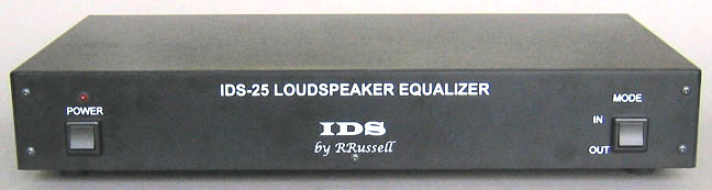
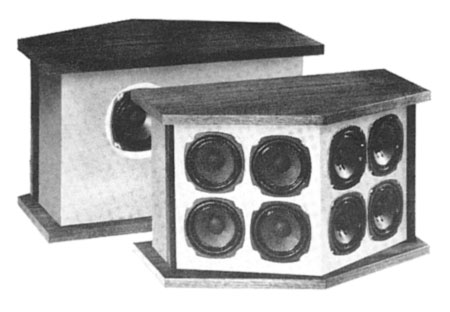
The IDS-25 system is also equalized and the curve is unique to complement the specific drivers used in the system. The large cone area, equivalent to a 16” woofer, can provide response to 20 Hz. The wide-range drivers are all connected in series parallel and cover most of the frequency range. The equalizer smoothes response and extends both low and high ends of the spectrum. The system is based on my patents and earlier work with equalizers and column systems.
In contrast to the Bose 901 system, the IDS system projects a near field further into the room even compared to conventional systems. This is because the sound of the long column arrangement of drivers decreases only 3dB when the distance is doubled instead of 6dB. In addition, the column design minimizes floor and ceiling reflections. All together, the room acoustics are not as influential on the sound in the recordings.
The driver magnet structure incorporates a copper cylinder around the magnetic pole piece. This greatly reduces the impedance at higher frequencies by lowering the voice coil inductance. At the same time it lowers the distortion by as much as a factor of ten.
Another advantage of the long wide-range column is that it has an acoustic gain of 10 dB over most of the frequency range compared to a single driver. This means that only one tenth of the power is needed for the same listening level.
Because all of the drivers are operated at full-range, no crossover networks are needed.
More Information on the IDS-25
|
About This Site |
||
|
|
|
More text and pictures about equalizers will be added as my research continues. Any comments, corrections, or additions are welcome. |
|
|
All
contents are copyright |
|